Documentation
Turbomachinery systems are pivotal to various key industries, including power generation, aerospace, and oil and gas. Turbomachinery equipment is designed to harness and control fluid energy and exchange this fluid energy with a rotor. From turbochargers in automobiles to turbines used in steam or hydroelectric power generation, turbomachinery plays a crucial role in our modern lives. In this article, we will delve into the fundamentals of turbomachinery, explore its types and applications, and understand how computational fluid dynamics (CFD) and finite element analysis (FEA) simulations are revolutionizing the design and performance optimization of these complex systems.
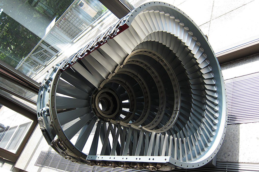
Turbomachinery refers to the class of machines that transfer energy between a moving fluid and a rotor. It consists of both turbines, which extract energy from the fluid, and compressors or fans, which impart energy to the fluid.
Turbines and compressors are essentially opposites in their function. While a compressor transfers energy into a fluid, raising its pressure, a turbine operates in reverse. It extracts energy from a fluid flow, reducing its pressure. Simply put, power must be input to compressors, and power will be output from turbines. In this section, we will give a brief overview of each.
Turbines are devices that extract energy from a fluid and convert it into useful work. For example, the blades of a large wind turbine connect to a central shaft, which then passes the wind power into a gearbox and eventually to an electric generator. Turbines are essential to efficiently extract power from sources of chemical, atomic, or environmental (wind, water, solar) energy.

The four most common types of turbines are:
Compressors are devices that increase the pressure of a fluid, typically gases, by mechanically imparting energy to them. They are crucial in various applications, such as gas pipelines, refrigeration systems, jet engines, and transportation.

The two main styles of compressors are:
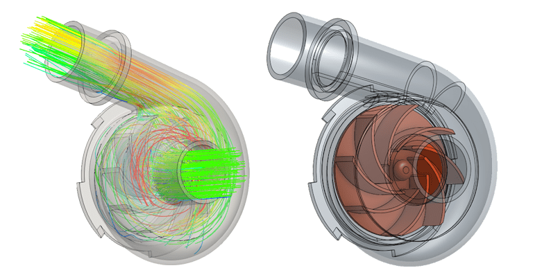
CFD simulations have emerged as a game-changer in turbomachinery design. By leveraging advanced computational methods, these simulations provide engineers with valuable insights into complex flow phenomena involving wall separation, boundary layer effects, and shockwaves in a three-dimensional virtual environment. This allows engineers to optimize component designs, improve compressor and/or turbine efficiency, and reduce other losses. Moreover, CFD simulations aid in identifying potential issues such as cavitation and allow for the evaluation of cooling techniques for gas turbine blades using conjugate heat transfer methods, ensuring effective heat dissipation and prolonging component life.
CFD serves as a practical, early-stage tool that engineers use in conjunction with experimental physical testing. The use of iterative CFD analysis offers several cost-saving advantages over experimental testing alone.
One key benefit is the reduction of physical prototypes needed to test. Traditional testing methods require the production of precise physical parts, which can be time-consuming and very expensive to produce in low quantities. CFD, on the other hand, allows engineers to quickly and virtually replicate the turbomachinery system or components, saving costs associated with manufacturing, assembly, and testing.
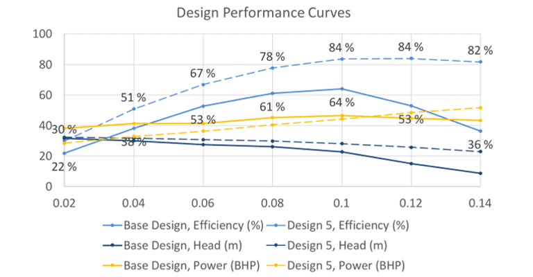
Using CFD, engineers can rapidly evaluate multiple design iterations in a short span of time, taking advantage of parallel cloud computing and automation. Various parameters such as blade geometry, flow paths, and operating conditions can be assessed and analyzed for key performance metrics without the need for time-consuming physical experiments. This iterative virtual simulation process helps optimize designs efficiently, leading to significant time and cost savings. Thus, the starting point for the requisite physical testing is greatly improved.

Much like physical testing, CFD simulation provides overall performance reporting and metrics. However, simulation results go well beyond these outputs and provide valuable insights into flow phenomena, pressure losses, and other characteristics. It would be very difficult or impossible to instrument a physical test to obtain even a fraction of this information. By accurately predicting the system’s behavior, potential issues can be identified, and areas for improvement can be addressed virtually, reducing the need for costly physical modifications and retesting.
With advancements in CFD techniques, including high-fidelity, transient turbulent physics, GPU acceleration, and integration with machine learning (AI) algorithms, there is tremendous potential for continued innovation in turbomachinery systems by leveraging this technology.
Finite Element Analysis (FEA) is another critical modeling tool used in turbomachinery design, enabling engineers to ensure structural integrity and efficient thermal management of complex systems. Through FEA modeling, engineers can evaluate the mechanical behavior of turbomachinery components, including rotor blades, casings, and housings. These simulations will predict the mechanical responses due to factors such as centrifugal forces and vibrations, thermal stresses, and fatigue life, allowing for the optimization of blade designs and reliable turbine operation.
FEA modeling allows engineers to evaluate the structural integrity of turbomachinery components under different operating conditions. The boundary conditions imposed on the FEA model are typically derived from previous experimental testing, simulations (including but not limited to CFD), and analytical predictions. By dividing the complex geometry into tiny finite elements, FEA accurately predicts three-dimensional stress and deformation distributions, identifying potential areas of concern. Specific components include turbine and compressor/fan blades, rotors, casings, combustion liners, and other critical components, ensuring their reliability and safety.
The rotational nature of turbomachinery dictates that cyclic loading, heating, and vibrations will happen. In order to model this, specialized FEA-based fatigue analysis tools are used to predict the life of turbomachinery components in operation. By considering the alternating stresses, thermal cycles, and material properties, engineers can estimate the amount of time before fatigue failure occurs. This information is vital for ensuring the reliability and durability of turbomachinery systems, particularly in applications with high rotational speeds and cyclic operating conditions, such as aircraft gas turbines.
Additionally, FEA and CFD are often used in tandem to conduct multi-disciplinary optimization of turbomachinery components. Due to the coupled nature of the aerodynamic shape, aerothermal heating/cooling, and structural integrity, CFD and FEA simulations may need to pass information to one another to get a complete physical simulation.
For example, FEA modeling enables the accurate assessment of thermal effects within turbine blades. It helps evaluate heat transfer characteristics, analyze temperature distributions, and identify potential hotspots where material failure could occur. FEA simulations would leverage the detailed results of a CFD simulation of both external heating and internal cooling flow paths. Cooling techniques can be optimized while minimizing the mass and stress concentrations in the blade. This is just one area in which engineers can deploy CFD and FEA to enhance thermal management and prevent overheating, which is crucial for the longevity and efficiency of the turbomachinery system.

Turbomachinery stands as a critical pillar of numerous industries, driving power generation, facilitating oil and gas processing, and propelling aerospace advancements. This diverse field encompasses various devices which play pivotal roles in converting energy, managing fluid flow, and moving goods and people. With the aid of cutting-edge technologies such as CFD and FEA simulations, engineers can optimize turbomachinery designs, enhance performance, and ensure structural integrity in a virtual environment before producing a single prototype.
The continuous advancements in these simulation techniques bode well for the future of turbomachinery, enabling more precise and efficient systems as the driving force for our world and beyond.
Last updated: August 11th, 2023
We appreciate and value your feedback.
What's Next
Cleanroom Classifications, ISO Standards, & DesignSign up for SimScale
and start simulating now