Cleanroom Classifications, ISO Standards, & Design
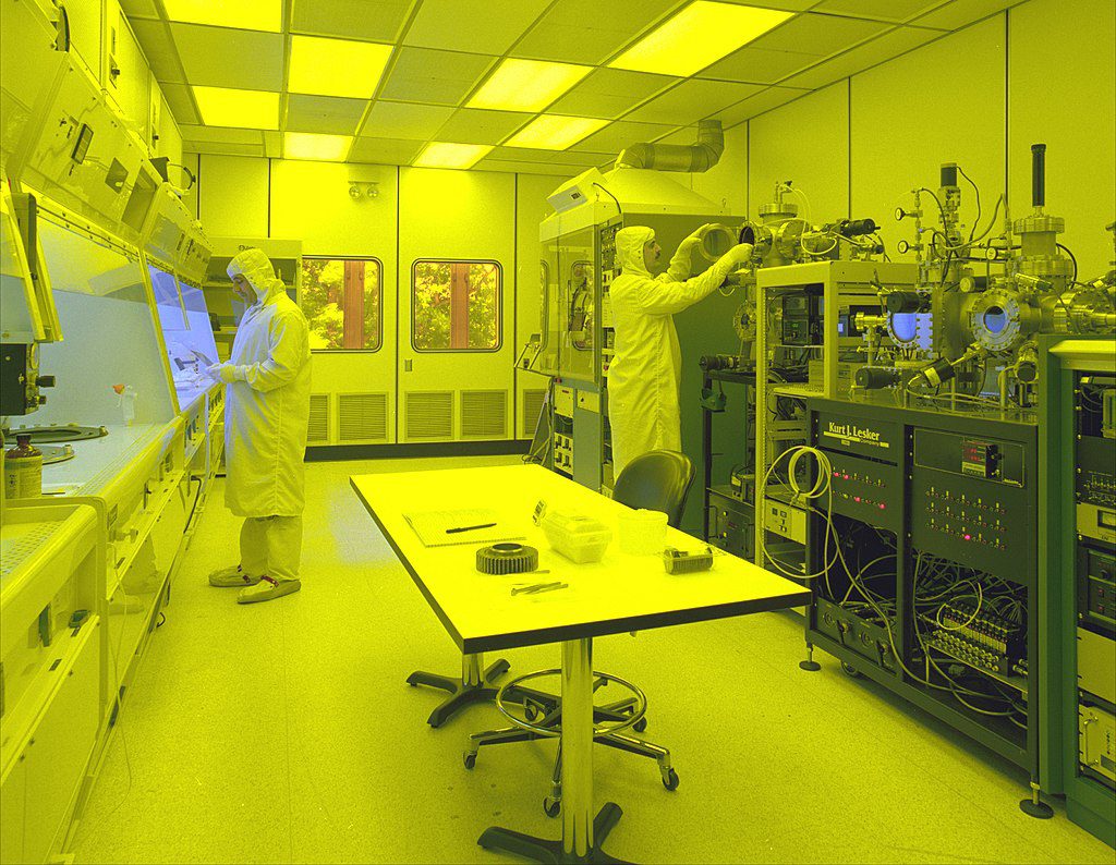
A cleanroom is a controlled environment that is designed to minimize the presence of airborne particles, dust, and contaminants in order to maintain a high level of cleanliness. Cleanrooms are used in various industries, such as pharmaceuticals, biotechnology, electronics, aerospace, and medical device manufacturing, where even a small particle or contamination can have significant consequences.
The main purpose of a cleanroom is to provide a controlled space where specific environmental conditions, such as air quality, temperature, humidity, and pressure, can be maintained within defined limits. These conditions are typically achieved through the use of specialized filtration systems, airflow control, and rigorous cleaning and maintenance procedures.
In general, cleanrooms are designed to maintain a unidirectional or laminar airflow pattern to minimize the contamination of the controlled environment. This is usually achieved by providing high-efficiency particulate air (HEPA) or ultra-low particulate air (ULPA) filters to remove particles from the supply air.
Cleanroom Classifications
Depending upon the industry/workspace, level of cleanliness, and ventilation requirements, clean rooms are classified with several standards. Cleanrooms and controlled environments are subject to various international standards and guidelines to ensure consistent performance and adherence to specific cleanliness levels. Here are some of the key standards related to cleanrooms:
- ISO 14644 Series:
- ISO 14644-1: Classification of air cleanliness in cleanrooms and controlled environments
- ISO 14644-2: Monitoring to provide evidence of cleanroom performance related to air cleanliness by particle concentration
- ISO 14644-3: Test methods for cleanroom performance related to air cleanliness by particle concentration
- ISO 14644-4: Design, construction, and start-up of cleanroom and clean air devices
- ISO 14644-5: Operations
- ISO 14644-6: Vocabulary
- ISO 14644-7: Separative devices (clean air hoods, gloveboxes, isolators, mini-environments)
- ISO 14644-8: Classification of airborne molecular contamination
- US Federal Standard 209E:
- Although it has been canceled and replaced by ISO 14644, it was a widely used standard for cleanroom classification, defining cleanroom classes and allowable airflow conditions.
- EU GMP Annex 1:
- The European Union’s Good Manufacturing Practice Annex 1 provides guidelines for sterile medicinal products and includes requirements for cleanroom design and operation.
- US FDA cGMP:
- The United States Food and Drug Administration’s current Good Manufacturing Practices include requirements for cleanrooms and controlled environments for the pharmaceutical and biotechnology industries.
- IEST-RP-CC001 Series:
- Recommended practices by the Institute of Environmental Sciences and Technology (IEST) that cover various aspects of cleanroom design, construction, and operation
- BS EN ISO 14644 Series:
- British and European versions of the ISO 14644 standard harmonized with the international ISO versions
- GMP (Good Manufacturing Practices) guidelines:
- Various countries have their own GMP guidelines specific to pharmaceutical and healthcare industries, which may include requirements for cleanrooms and controlled environments.
Often, the Air changes per hour (ACH) is used as a supplementary measure for cleanrooms in addition to the standards. To calculate the air changes per hour (ACH) from a volumetric flow rate in a cleanroom, you’ll need to know the volume of the cleanroom space. The formula for calculating ACH is as follows:
$$ ACH =\left(\frac{Volumetric\,Flow\,Rate}{Cleanroom\,Volume}\right) \times 60 $$
Where:
- ACH is the air changes per hour.
- Volumetric Flow Rate is the rate at which air is supplied or exhausted from the cleanroom, usually measured in cubic feet per minute (CFM) or cubic meters per hour (m³/h).
- Cleanroom Volume is the total volume of the cleanroom space, typically measured in cubic feet (ft³) or cubic meters (m³).
Among the standards mentioned, ISO 14644-1 is commonly used and widely recognized in the industry. In the next section, we will look into the criteria and applications with respect to the standard.
ISO Cleanroom Standards
ISO 14644-1 is the widely accepted and commonly used standard that addresses various cleanroom requirements. It classifies cleanrooms from ISO 1 to ISO 9, with ISO 1 being the most demanding in terms of cleanliness levels.
Standard Designation
The designation of airborne particle concentration for cleanrooms and clean zones shall include:
- The ISO Class number, expressed as “ISO Class N”,
- The occupancy state to which the classification applies, and
- The considered particle size(s).
| ISO 14644-1:2015 Class N | ≥ 0.1 μm (particles/m³) | ≥ 0.2 μm (particles/m³) | ≥ 0.3 μm (particles/m³) | ≥ 0.5 μm (particles/m³) | ≥ 1 μm (particles/m³) | ≥ 5 μm (particles/m³) |
|---|---|---|---|---|---|---|
| ISO 1 | 10 | Not specified | Not specified | Not specified | Not specified | Not specified |
| ISO 2 | 10 | 2 | 1 | 1 | 1 | 1 |
| ISO 3 | 1 | 237 | 102 | 35 | Not defined | Not defined |
| ISO 4 | 10 | 2.37 | 1.02 | 352 | 83 | Not defined |
| ISO 5 | 100 | 23.7 | 10.2 | 3.52 | 832 | |
| ISO 6 | 1.000.000 | 237 | 102 | 35.2 | 8.32 | 293 |
| ISO 7 | Not defined | Not defined | Not defined | 352 | 83.2 | 2.93 |
| ISO 8 | Not defined | Not defined | Not defined | 3.520.000 | 832 | 29.3 |
| ISO 9 | Not defined | Not defined | Not defined | 35.200.000 | 8.320.000 | 293 |
| ISO 14644-1:2015 Class N | Example cleanroom environments |
|---|---|
| ISO 1 | Semiconductor manufacturing, nanotechnology research facilities, and precision device manufacturing |
| ISO 2 | Standard pharmaceutical manufacturing, medical device assembly, and packaging areas |
| ISO 3 | Pharmaceutical compounding, advanced medical device manufacturing |
| ISO 4 | Standard pharmaceutical manufacturing, medical device assembly and packaging areas |
| ISO 5 | Hospital operating rooms and surgical suites, standard pharmaceutical packaging areas |
| ISO 6 ISO 7 ISO 8 | Sterile and non-sterile compounding pharmacies, some laboratory and research areas with moderate cleanliness requirements, food-processing and food-packaging facilities |
| ISO 9 | Office spaces or adjacent non-critical areas in controlled environments, storage rooms in pharmaceutical or electronics manufacturing facilities, some retail or commercial environments where a minimal level of particle control is required |
It’s important to note that these examples are general guidelines and the specific application of each cleanroom class may vary depending on the industry, regional regulations, and company-specific requirements. Cleanroom design and classification should always be carefully tailored to the specific needs and cleanliness levels required for the products and processes conducted within the controlled environment.
Cleanroom Ventilation
It’s important to note that cleanroom airflow/ventilation requirements are highly dependent on the specific needs of the cleanroom application, and they should be determined and validated during the cleanroom design and commissioning phase.
The effectiveness of the air system in removing airborne particles in cleanrooms and controlled environments is influenced by the type of airflow concept used. There are three main types of airflow concepts employed for contamination control:
Unidirectional Airflow
In cleanrooms with unidirectional airflow, the air moves in a single, uniform direction, typically from a filtered ceiling down to the floor. This unidirectional flow creates a consistent and controlled path for airborne particles, reducing the risk of particle recirculation and ensuring efficient particle removal.
Non-Unidirectional Airflow
Non-unidirectional airflow does not have a singular, defined direction of airflow. Instead, the air may move in various directions, creating a more turbulent environment. While non-unidirectional airflow can be adequate for certain applications, it may be less effective in achieving stringent cleanliness levels, as it can lead to particle recirculation and dispersion.
Combined Airflow
As the name suggests, combined airflow incorporates elements of both unidirectional and non-unidirectional airflow. This concept may involve using unidirectional airflow in critical areas or around specific equipment while allowing non-unidirectional airflow in less critical zones. The combined approach aims to balance contamination control requirements with practical considerations, offering more flexibility in cleanroom design.
Each airflow concept has its advantages and limitations, and the choice depends on the specific cleanroom requirements, the activities performed within the controlled environment, and the cleanliness level needed for the processes or products involved. Cleanroom designers carefully consider these factors to select the most appropriate airflow concept to achieve optimal particle control and contamination mitigation.
Note
ISO 14644-4:2022 notes that some applications can require a combination of different airflow types/directions to both maintain cleanliness and contain hazards.
Cleanroom Design Using CFD
Designing a cleanroom requires careful consideration of various factors to meet the specific needs of the intended application and industry. Here are some of the major requirements to consider while designing a cleanroom:
- Cleanroom class and ISO standard
- Size and layout
- HVAC / contamination extraction system
- Lighting
Designing a successful cleanroom requires collaboration between cleanroom designers, HVAC engineers, contamination control experts, and industry professionals to create a controlled environment that meets the specific requirements of the application while ensuring the highest level of cleanliness and product integrity.
A cleanroom design can start with barely an analytical solution to capture the required Airflow changes according to the considered application. But it soon becomes complex when we need to consider other factors in the design. While physical prototyping can be beneficial in some design and testing scenarios, it also has some disadvantages when it comes to:
- Amount of time required to construct and assemble the actual scenario,
- Limited flexibility on changing/testing different configurations
- Difficulty in scaling when in need of customization
- Limitations in terms of measuring and analyzing airflow, humidity, or temperature at different locations inside the cleanroom
- Safety concerns, especially if the testing involves hazardous substances in a partially controlled environment
Engineers and designers often turn to Computational Fluid Dynamics (CFD) simulations and other virtual modeling tools to enhance cleanroom design. CFD provides valuable insights into the complex dynamics of airflow and contamination control, enabling comprehensive assessments of the cleanroom environment. By utilizing CFD, designers can explore various configurations, optimize airflow patterns, and predict real-world scenarios without the need for physical prototypes. The flexibility of CFD allows for iterative design improvements, ensuring efficient, safe, and compliant cleanroom facilities. Moreover, CFD visualizations facilitate better understanding and communication of results, aiding in the decision-making process for achieving the desired cleanliness levels.
Simulating Cleanroom Ventilation
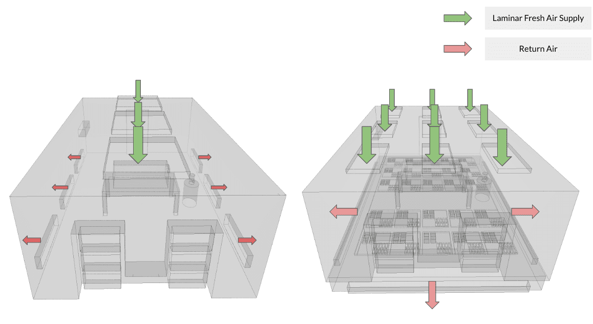
In this section, we analyze a typical cleanroom utilized in the biomedical and pharmaceutical industry using Computational Fluid Dynamics (CFD). The study aims to compare two different ventilation designs and assess their effectiveness in extracting contamination within the cleanroom. The base design (Design A) features three laminar flow diffusers located on the ceiling, along with a series of return flow ducts positioned on the side walls. In contrast, the modified design (Design B) incorporates nine laminar flow diffusers and an underfloor return system. By conducting this comparative analysis, we aim to gain insights into the cleanroom’s ventilation performance and identify the most efficient design to maintain optimal cleanliness and contamination control during biomedical and pharmaceutical processes.
Both designs aim to completely extract the contamination source present near the working area using their respective ventilation systems. The study focuses on key results, such as flow uniformity, air changes per hour, and resident contamination, to assess and compare the cleanroom ventilation performance of these two designs. By analyzing these crucial factors, the most effective ventilation approach can be identified to ensure optimal cleanliness and safety within the cleanroom environment.
| Parameter | Design 1 | Design 2 |
|---|---|---|
| Room Volume | 241 m2 | 288.5 m2 |
| Air changes per hour | 13.5 | 11.2 |
Below are some design constraints used in this study:
- HVAC supply flow rate < 0.9 m³/s
- Achieve unidirectional flow throughout the space
- Improve contamination extraction
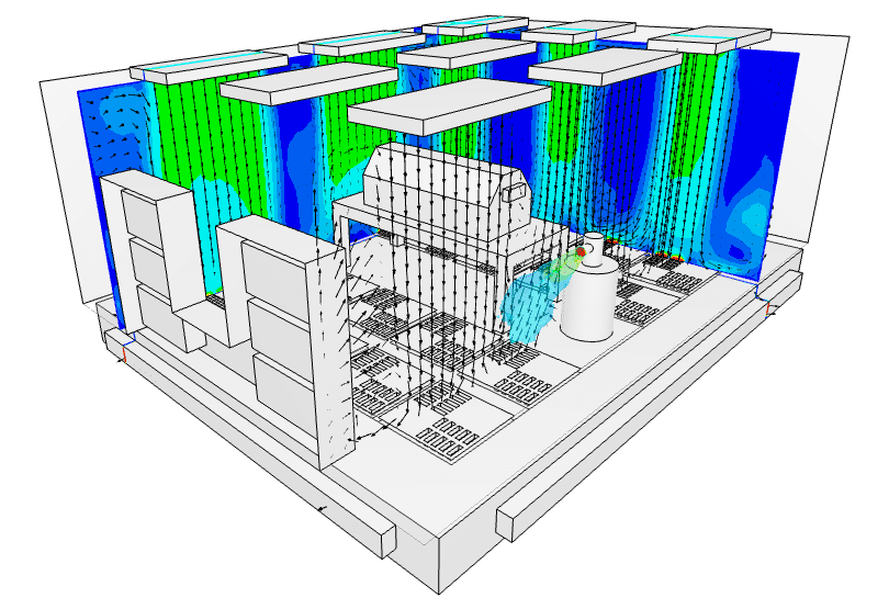
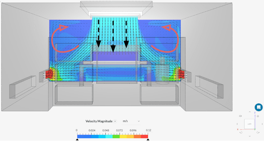
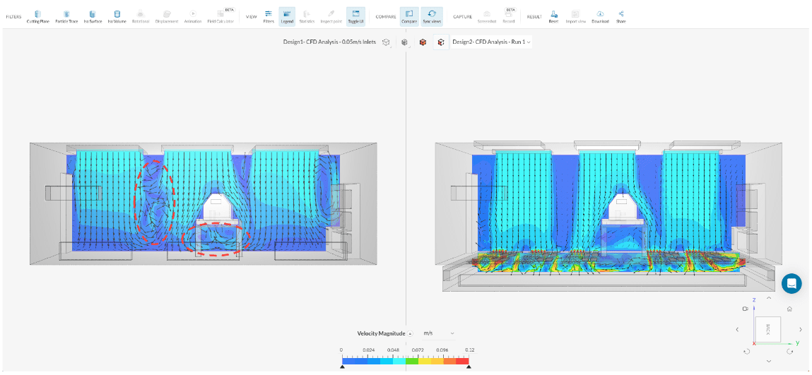
The CFD analysis of the base design in Figure 4 shows that the unidirectional flow is primarily concentrated below the inlet, but it then drifts towards the outlet, leading to stagnant or recirculating zones in the upper section of the room. Consequently, this layout increases the likelihood of stagnant contamination lingering near the source.
In contrast, the design variant featuring multiple inlet diffusers and an underfloor return air system divides the inlet draft into several uniform flow drafts, which are effectively extracted through the floor. This underfloor extraction method helps maintain a more consistent unidirectional flow compared to the base design. As a result, the cleanroom benefits from improved airflow distribution and reduced chances of contamination build-up near the source.
Apart from examining the flow characteristics, the spread of contamination can be effectively compared using an Iso volume filter. This additional analysis provides valuable insights into how contaminants disperse and accumulate within the cleanroom environment.
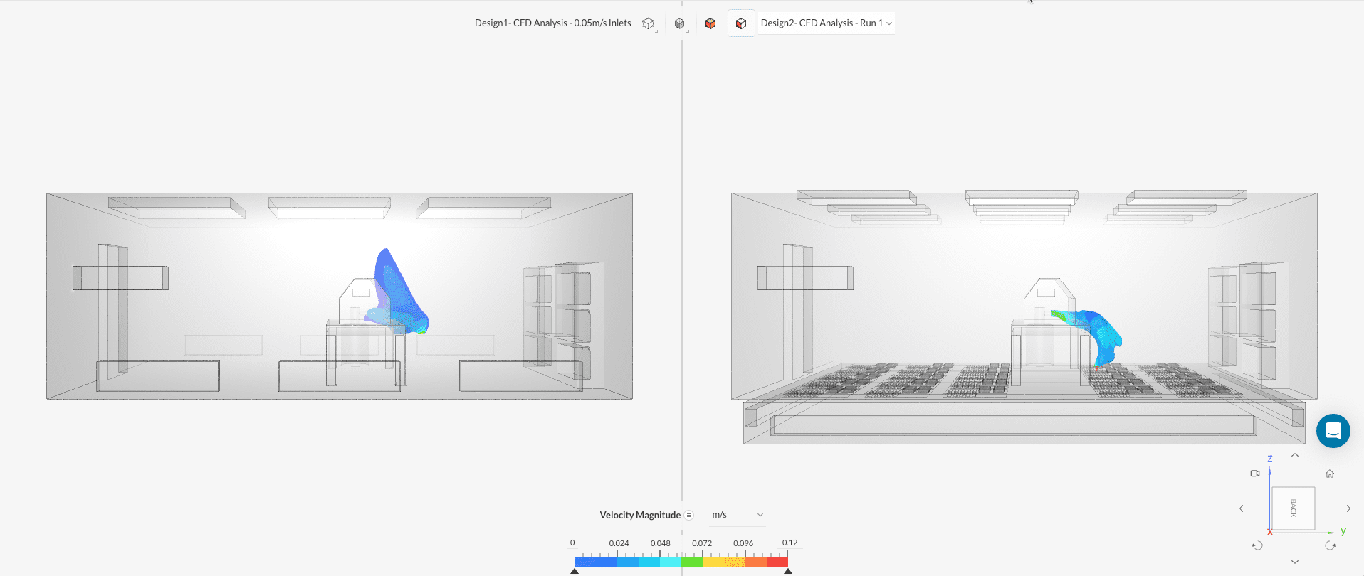
In Figure 6, a noticeable distinction can be observed between the two designs. In the base design, contaminants are observed rising from the source due to recirculation effects occurring between the inlet drafts. On the other hand, design B, which incorporates underfloor extraction, proves to be more effective. It successfully keeps the contamination below human face level and efficiently directs it into the return system. The utilization of underfloor extraction significantly improves the cleanroom’s contamination control capabilities, ensuring a safer and cleaner environment for personnel and critical processes.
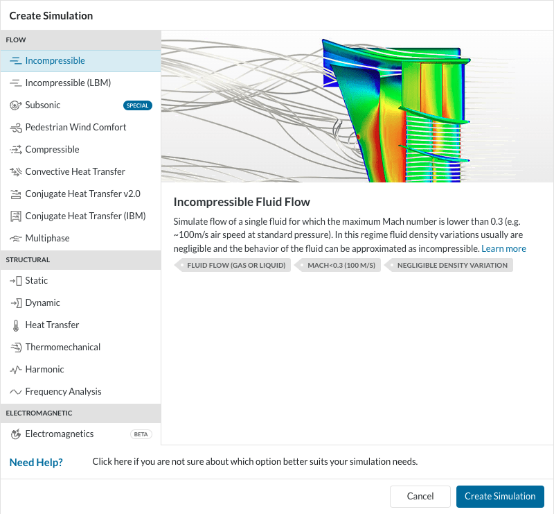
The above simulations were performed using the incompressible analysis type in SimScale with a passive scalar approach for the contamination spread. The example case can be found here for reference: Cleanroom Ventilation Study.
In summary, by incorporating CFD in cleanroom designs, designers can gain a comprehensive understanding of contamination patterns and make informed decisions to optimize cleanroom layouts and ventilation systems. The combination of flow analysis and contamination spread evaluation empowers cleanroom designers to create efficient, reliable, and highly controlled environments, meeting the stringent standards required for various industries such as pharmaceuticals, biotechnology, and microelectronics.
With SimScale’s CFD simulation tool, designers can solve complex flow equations using accurate numerical methods, robust turbulence models, and complex CAD-handling solvers, all in one tool. SimScale’s cloud-native platform enables engineers and designers to access, run, and share simulations anytime, anywhere, simply in their web browser. This not only accelerates analysis, design, and innovation but also helps minimize costs associated with physical testing and prototyping. Hear from SimScale customers Kohler Ronan and Architype how they leveraged the SimScale platform to speed up their analyses by running multiple simulations in parallel and link cloud-based CFD to their energy savings from thermal modeling and analysis.
Last updated: August 25th, 2023
Did this article solve your issue?
How can we do better?
We appreciate and value your feedback.
What's Next
What Is FEA? Finite Element Analysis Explained

