Contacts
Contacts are necessary in cases when the simulation domain doesn’t consist of one part – built from a single material, but an assembly of parts, often built from different materials, and even combining fluids and solids in the case of multi-physics simulations. A realistic model requires a setup where the relations between the multiple components are fully defined.
SimScale accepts multi-part models for simulation in the following domains:
Solid Mechanics
In terms of contact definitions, solid mechanics simulations include:
For these simulations, a distinction is made between linear and non-linear (physical) contacts. Linear contacts work under the assumption that the parts remain bonded or have small relative deformations, while non-linear contacts can take into account large sliding, separation and collision between the parts.
In the following pages, the details on the modeling and setup of contacts and solid mechanics are given:
Conformal Meshing
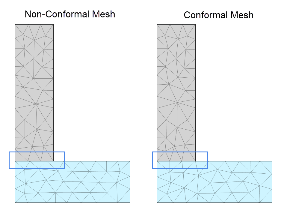
When using conformal meshing the nodes on a contact face are merged into a single node. This means that the two parts in contact share the same nodes on the contact face. Thus the face of a contact will result in a conformal mesh. SimScale allows the user to activate conformal meshing for all structural simulation types. This can be activated in the general contact setting as seen in Figure 1.

Figure 2 shows the difference between a conformal mesh and a non-conformal mesh. It can be seen that the nodes on the contacting face are merged into a single node, whereas for the non-conformal mesh, the nodes on each face are offset.
Node Merging with Sweep Meshing
When using a automatic extrusion meshing or extrusion mesh refinement it might not be possible to create conformal meshing due to restrictions from the sweep mesh conditions, causing the meshing to fail. In such cases please evaluate the mesh settings, or reach out to our support.
Conjugate Heat Transfer
For the Conjugate Heat Transfer solver, the contacts are also referred to as ‘interfaces‘. The interfaces can be between two solids or between a solid and a fluid, and allow to capture the heat transfer between the parts. More details about interfaces in heat transfer can be found in the following page:
Conflict Resolution and Optimization
The two surfaces that are in contact are classified as Master and Slave. Every node in the slave surface (slave nodes) is tied to a node in the master surface (master node) by a constraint.
- Please be aware that one face can not be the slave assignment of multiple contact definitions simultaneously. This also applies to shared edges and nodes between surfaces of different contact definitions.
- There are some general rules that help you to decide which of the contact faces or sets to choose as master and which to choose as slave entities. Although those rules do not apply strictly in every case, they provide a good starting point. Choose as slave entities, face(s) if:
- it is considerably smaller than its counterpart.
- it is more curved, compared to the other part of the contact pair.
- it belongs to the more flexible part, especially if the other part is constrained in displacement.
- it has a considerably finer mesh than its counterpart.
Automatic contact detection tries to always find an optimized solution, therefore it is preferable to use automatic contact detection instead of manually constraining the system. Conflicting contacts are marked with a warning icon in the contact list. A more detailed description of the conflict type and how to resolve it can be found on top of the contact settings panel.
Another warning in case of remaining conflicts is shown on run creation, along with an additional check to detect underconstraints in the system.
In case conflicts can not be resolved manually or by automatic contact detection, consider imprinting your CAD geometry.
Last updated: April 30th, 2025
Did this article solve your issue?
How can we do better?
We appreciate and value your feedback.


