CAD Editing
SimScale offers an integrated environment to interact with your CAD model and perform CAD-related operations.
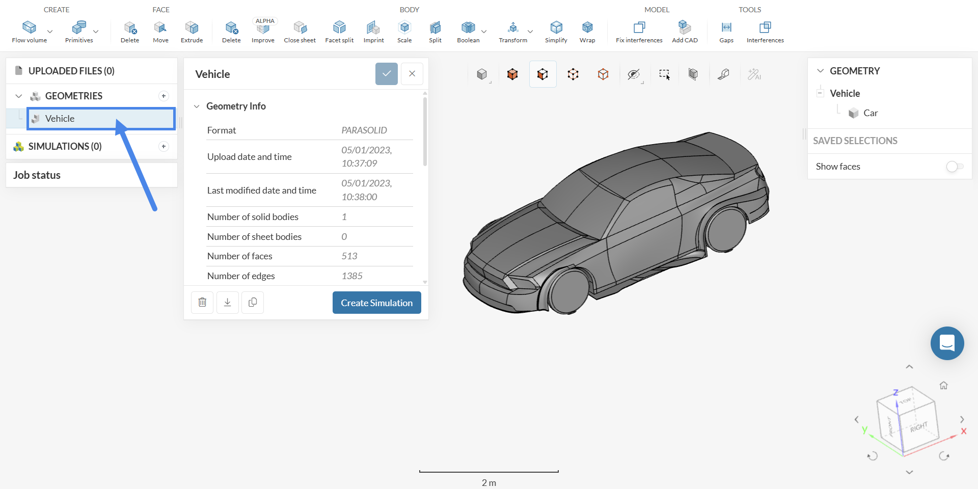
Within the Workbench, users can execute CAD operations to generate features such as flow volume extraction, deletion, extrusion, scaling CAD parts, amongst others. SimScale saves each CAD modification automatically. To edit a CAD model from the Workbench, select the imported geometry and start editing it as shown in the next figure:
CAD Editing Interface
The interface for CAD editing opens in the CAD context. If a user is editing simulations, then CAD editing interface will be hidden. The next figure shows the interface:
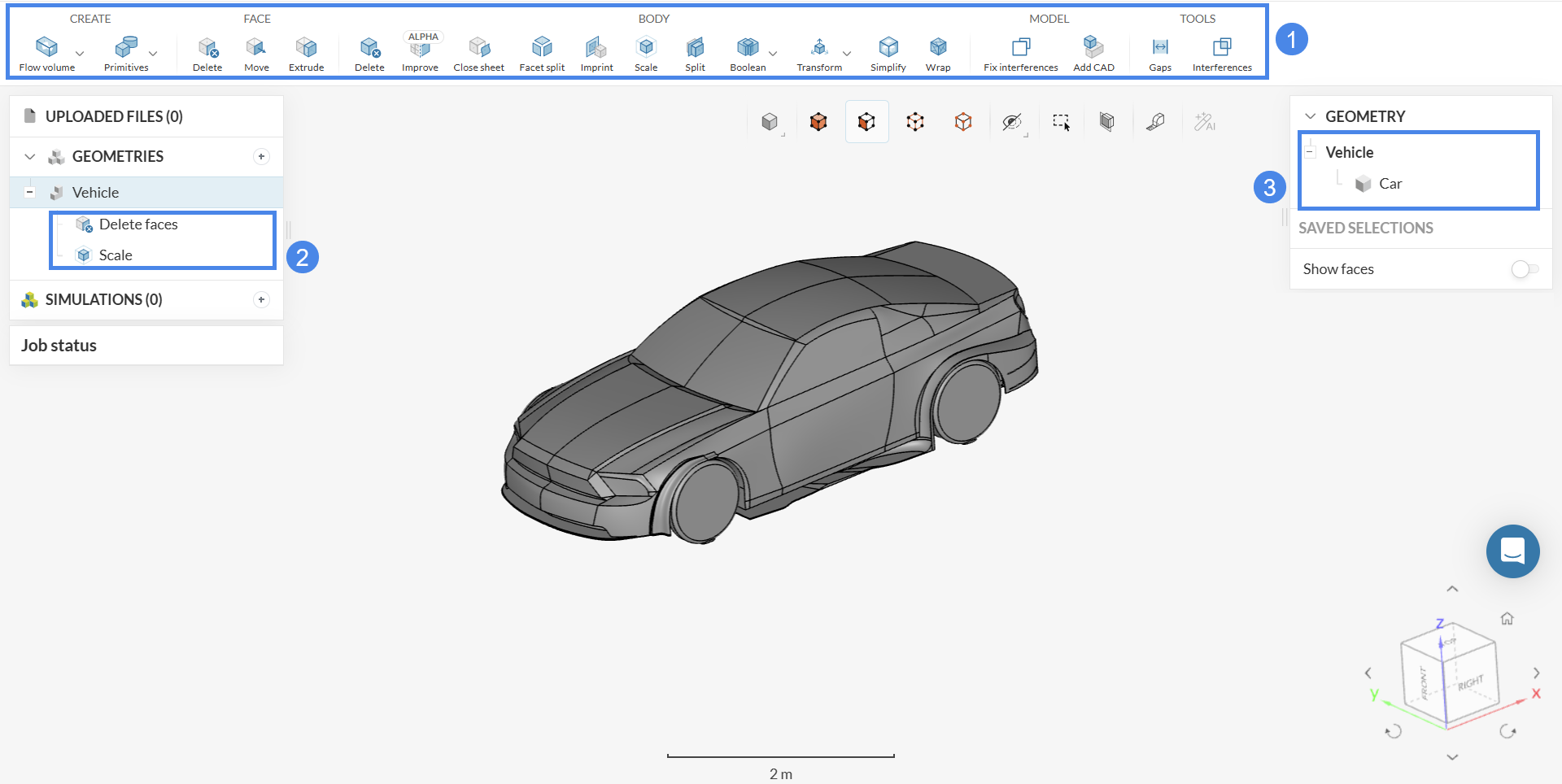
- CAD Operations Toolbar: Contains all supported CAD operations. All the operations are further explained in this document.
- CAD Feature List: Displays the history of the features applied to the CAD (features are results of a CAD operation).
- Scene Tree: Lists the original geometry with its solid bodies and faces. Toggle Show faces to see and keep track of all the faces of each solid body present in the geometry.
Updating a CAD model in a simulation
A user can modify a CAD model that is assigned to a simulation and manually update the edited CAD model in the simulation. Let’s see this workflow with an example.
A user assigns a CAD model to a simulation:
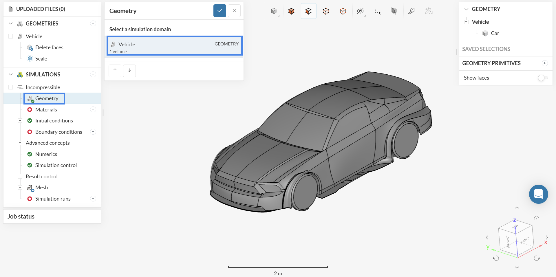
The user realizes that the CAD model has no flow volume; therefore, the user creates one by clicking on the CAD model in the GEOMETRIES tree and editing it.

Upon CAD modifications, SimScale indicates that the CAD model in the simulation is outdated by displaying a circular arrows and a yellow warning icon. SimScale does not automatically update the geometry in the simulation to the latest state. It must be done manually.
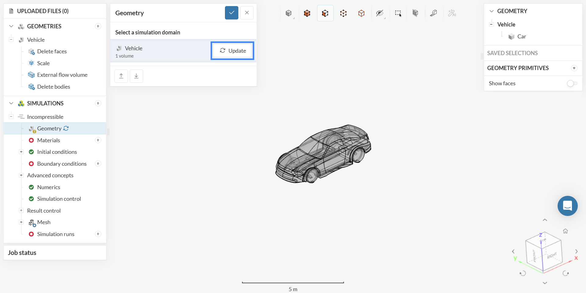
When the user clicks on the geometry in the simulation, SimScale shows the CAD model without the latest CAD modifications (the CAD is the same as the last time when the user edited simulation setup). The user then has two options:
- Use the geometry without the CAD modifications: If the user would like to simulate the geometry without the CAD modifications (i.e., without the flow volume), the user doesn’t need to do anything besides setting up the simulation and running it.
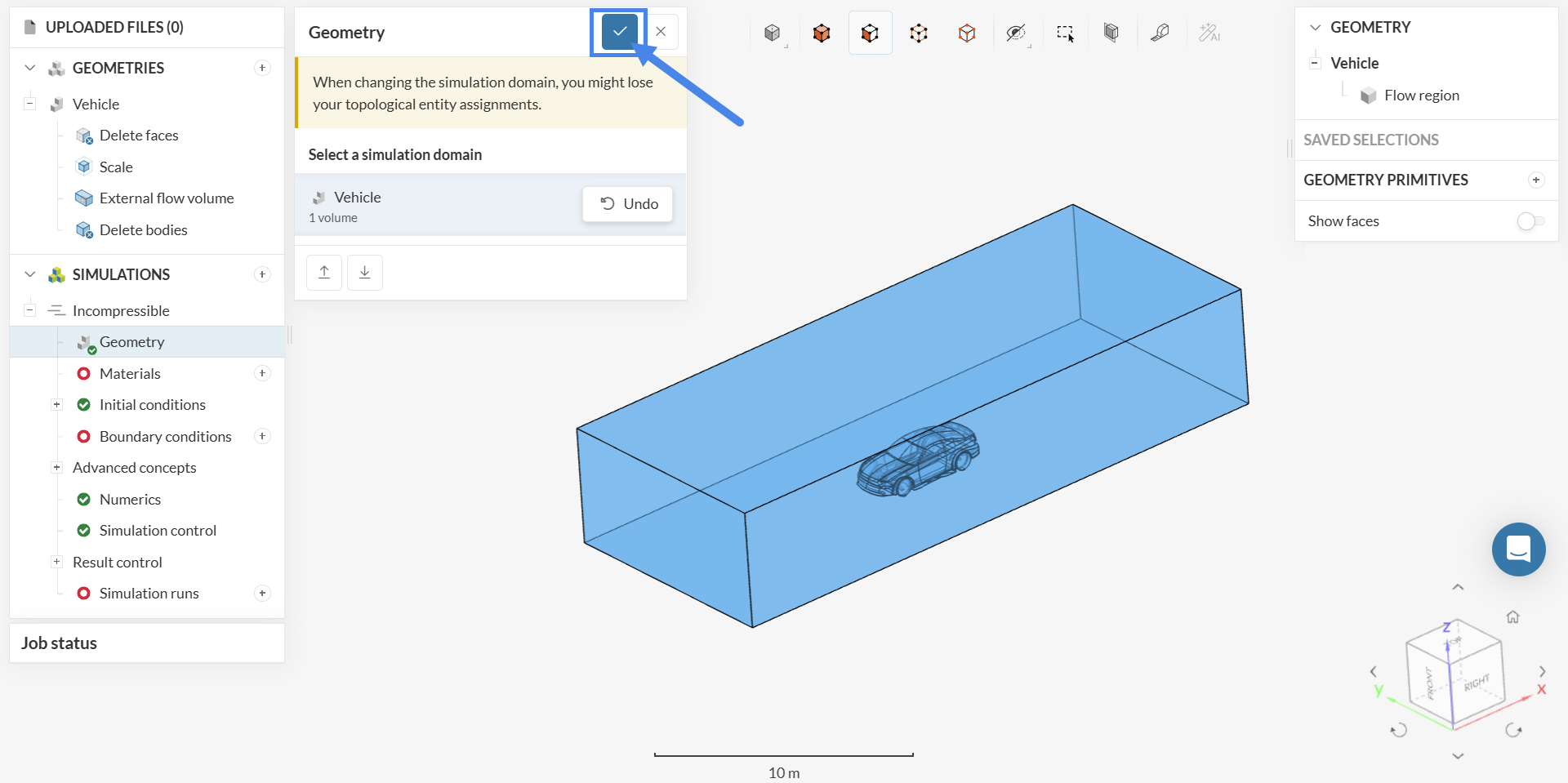
- Accept the changes and update the simulation geometry: If the user would like to simulate the geometry with the CAD modifications (i.e., with the flow volume), then the user clicks Update button in the Geometry panel (which opens after clicking on the Geometry item in the simulation tree as shown in the above figure) and confirms the update (using the blue checkmark on the top right, as shown in the figure below). SimScale will then swap the CAD geometry and provide feedback about the mapped entities in the simulation assignments.
CAD Operations
The following operations are supported with more coming soon. The operations are categorized based on their application.
Face
Delete face
The Delete operation helps you to delete a face from the CAD model by selecting ‘Delete’ from the operations toolbar and then assigning one or multiple faces to be deleted.
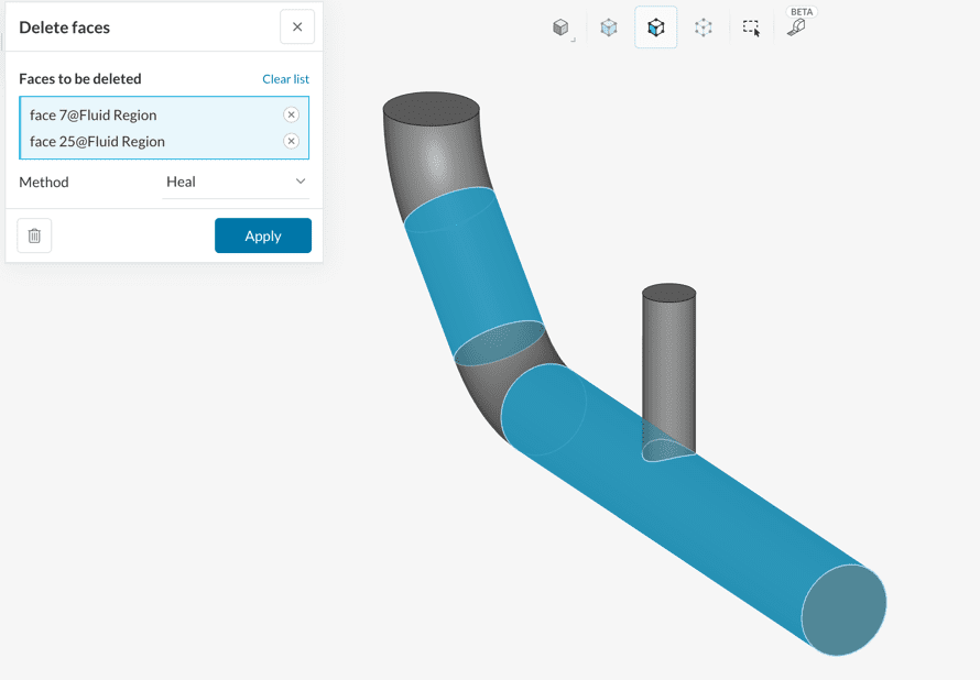
The settings panel also allows choosing between the available healing methods, viz. Heal and cap while the face delete operation is being performed. Choose Leave Open to opt out.
In the following section, all the healing methods are described using simple geometry as follows:
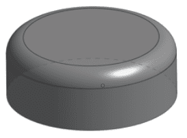
The reference geometry is a cylinder with one of its edges rounded to produce 1 curved and 3 planar faces.
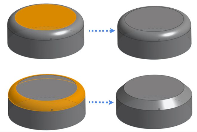
Heal
The Heal method will try to fill up the surface lost to the delete operation by trying to either expand or contract the adjacent faces until they intersect.
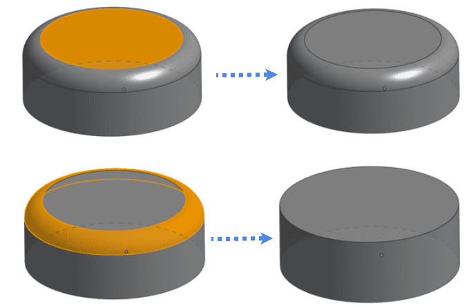
Cap
The Cap healing method will try to fill up the surface lost to the delete operation by connecting the adjacent faces without changing them.
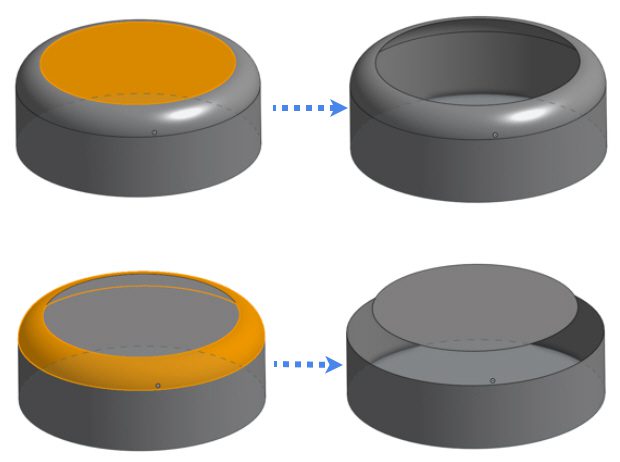
Leave Open
This healing method will leave a void as a result of the face delete operation and no additional efforts will be taken to heal the connecting faces.
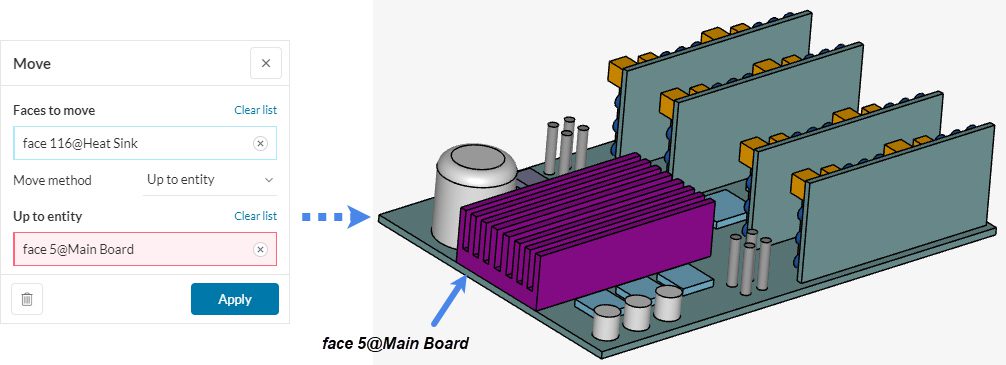
Move
With the Move operation, you can move a face in the direction of its normal. Select ‘Move’ from the operations toolbar to open the settings panel for this operation. There are two methods to move faces. For illustration let’s consider the highlighted heat sink face:
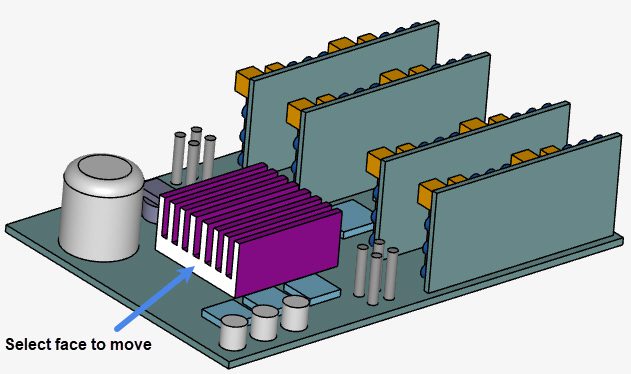
First, select the face and then choose one of the following methods:
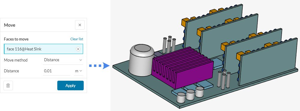
Distance
Specify the distance up to which the selected faces need to be moved/extruded.
Up to Entity
Specify the entity face up to which the selected faces need to be moved.
Important
The move operation will fail if it causes intersections of the same body. In such case use the Extrude > Merge > Up to entity option.
Extrude
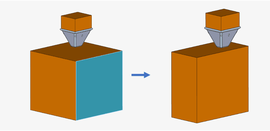
With the Extrude operation, you can extrude a face in the direction of its normal by specifying the distance or the face of an entity up to which it should extrude. Select ‘Extrude’ from the operations toolbar to open the settings panel for this operation. There are three methods to extrude faces. For illustration let’s consider the highlighted-blue face:
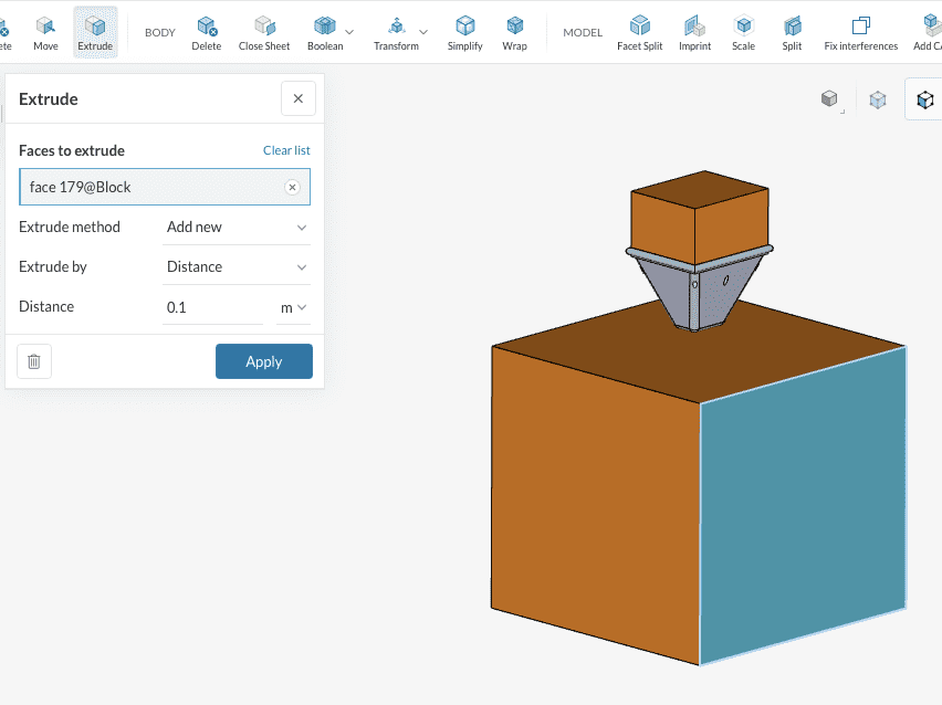
First, select the face and then choose one of the following methods:
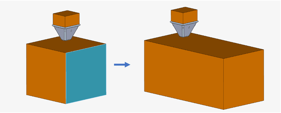
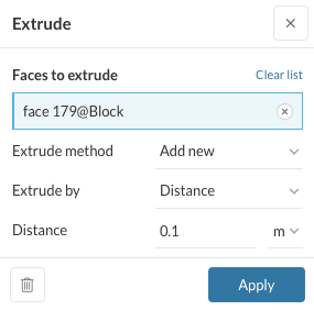
Add New
Add a new face to the existing one, while it is extruded in the normal direction. This operation creates an additional part.
Did you know?
Using a negative value in the Add new type extrusion would result in the removal of a part of the geometry dividing it into two parts instead of adding a new part.
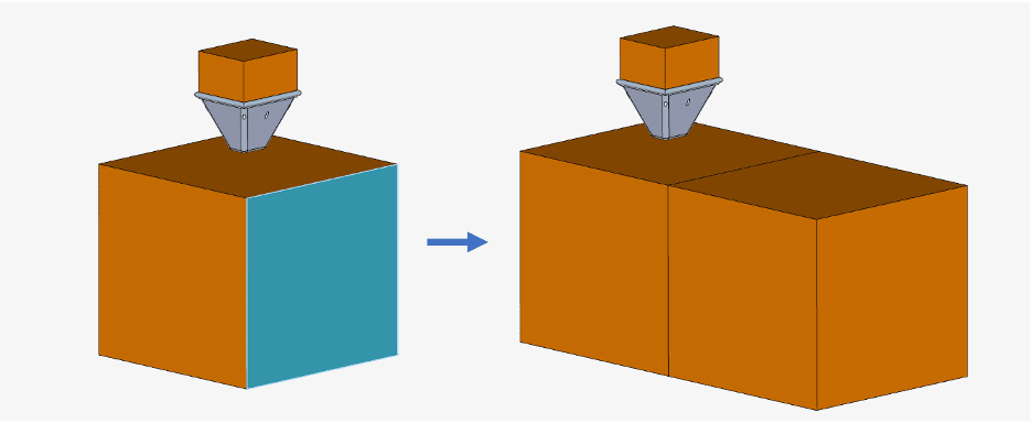
Merge
Extrude the face, merging it with the previous one. Thus, the number of parts remains the same.
Remove
Extrudes the face in the normal opposite direction, giving a removal operation.
Important
To perform extrude operation on multiple faces at the same time, ensure that all selected faces have the same normal.
Distance
Specify the distance up to which the selected faces need to be extruded. All those Extruded operations in this section were made using the distance extrusion method.
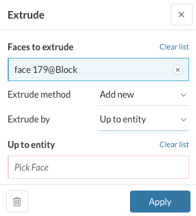
Up to Entity
Specify the entity face up to which the selected faces need to be extruded.
Body
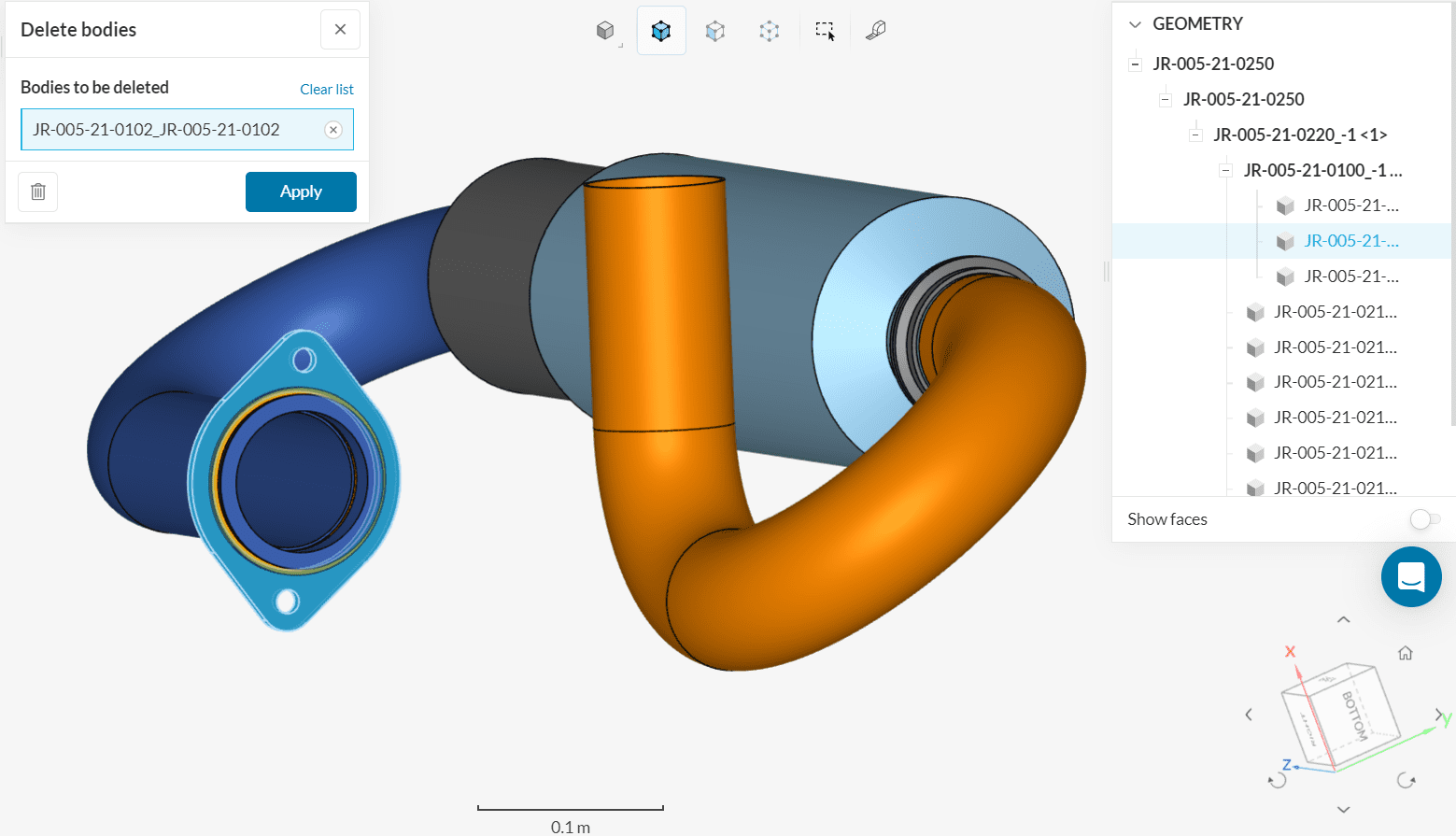
Delete body
The Delete operation will delete the solid bodies present in the CAD model. Click on ‘Delete’ under Body in the operations toolbar and assign one or more volumes from your CAD model before hitting ‘Apply’.
Close Sheet
There are instances where the CAD is missing one or more faces (these CAD models are called sheet bodies) and you are unable to proceed in the simulation process. In such cases the Close Sheet operation for bodies (volumes) is helpful. In the settings panel, select the bodies with missing faces to close and choose a closing method.
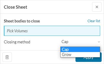
Closing Method
The Closing method defines how to close the sheet body using either the Cap or the Grow method. These methods are described below using an example of Crystal Towers:
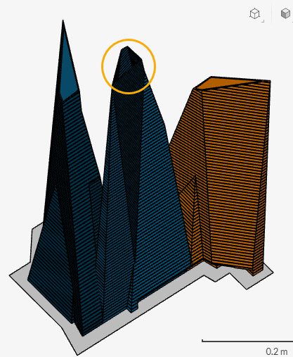
The tower in the middle has a missing face on the top. Hence, the close sheet operation is perfect for this CAD model.
Cap
The Cap method looks for the minimum possible surface path to close the sheet body and is the default closing method.
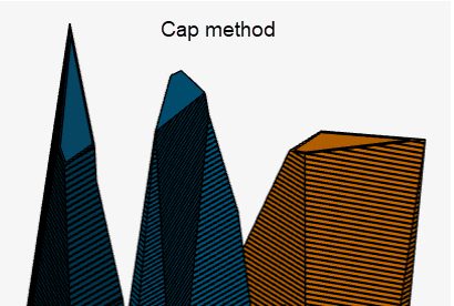
Applying this method to the middle tower closes the top face with minimum possible surface area.
Grow
The Grow method will try to extend the connecting faces to the missing face until they meet at a vertex.
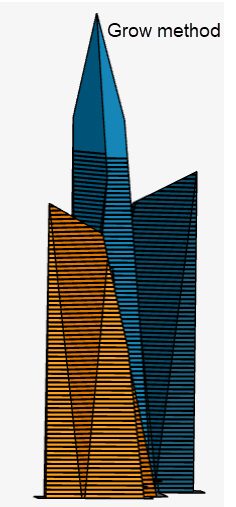
Applying this method by picking up the middle tower extends the connecting faces of the missing face elongating the middle tower until they all meet at a point.
Facet Split
Facet Split allows users to split the CAD model into multiple faces based on the defined maximum split angle. This operation comes in handy when dealing with .stl files as they often consist of only a single face.
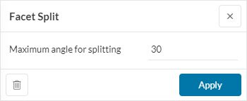
The angle can be added in degrees between 0 and 180 and is by default 30.
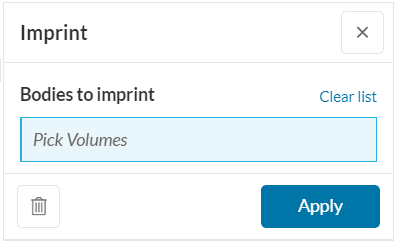
Imprint
In order to detect interfaces between two solids or a solid and a fluid, we need to perform an imprint. This action cuts the interface between two bodies that are in physical contact into recognizable surfaces. Please refer to our article where a detailed explanation of what an imprint does is well mentioned.
In the CAD mode, click on ‘Imprint’, then assign all the parts that need to be imprinted, and hit ‘Apply’.
Scale
In case the uploaded model does not match the original dimensions or the dimensions of your choice, the Scaling operation can be used to adapt the model size accordingly. With scaling, the simulation setup parameters might also change and care should be taken to avoid unreliable results.
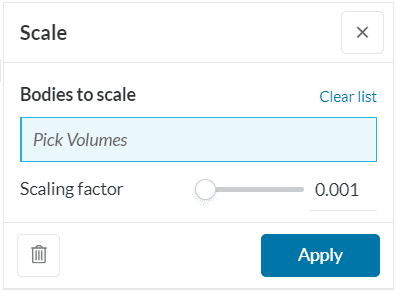
Assign all the bodies that need to be scaled. The settings panel also contains a slider to set a scaling factor while also allowing direct entry of the value.
Split
The Split operation allows users to cut individual CAD bodies into two parts based on the position and the orientation of the plane defined.
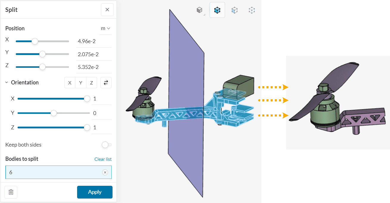
The orientation of the splitting plane is defined by specifying the normal to the plane. The part lying on the side where the normal vector points is retained, while the other part is removed. The user has the option to keep parts from both sides of the plane as well.
Boolean
You might run into situations where your CAD model has multiple overlapping parts. This might pose a hindrance to the simulation physics causing the simulation setup to fail. If this is the case try our set of Boolean operations. These operations allow you to perform union, subtraction, and intersection operations between different parts. These are described below:
Important
To perform the boolean operations the user must select two or more bodies that share overlapping volumes. If there are assigned bodies that don’t overlap they will be excluded from the operation. Even if no parts overlap, the operation will still show as successful but no changes will be shown in the viewer and in the scene tree.
Union
The Union operation is used to merge two overlapping entities into a single entity. The resulting body encloses the volume of both overlapping entities. This is shown below:
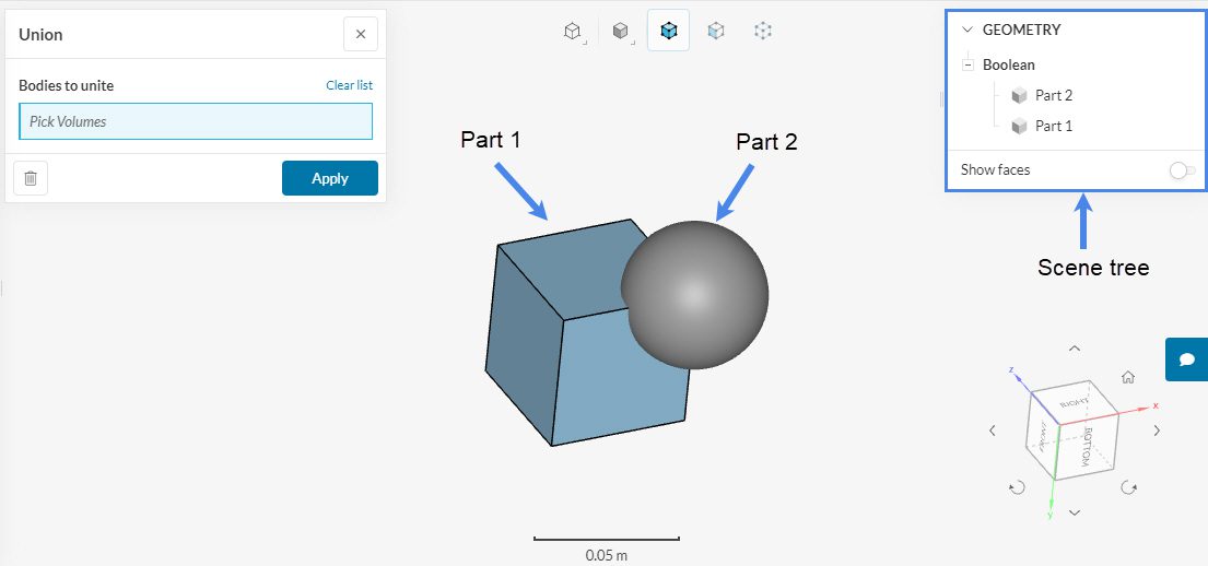
The CAD geometry consists of two overlapping bodies, Part 1 (cube) and Part 2 (sphere). Their different colors represent two separate entities. These two bodies are separately identified in the scene tree. To perform the Union operation select the two bodies and hit ‘Apply’.
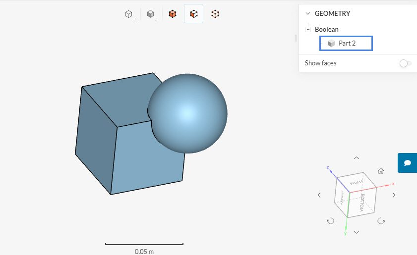
On success, the CAD geometry shows a single body identified with the name Part 2 in the scene tree and the same color. This signifies that the two bodies are united into one single body.
Intersect
The Intersect operation is used to create a new entity out of the common volume between the overlapping entities. You just need to select the involved entities. Using the same example as in Figure 27 the intersection operation results in the following CAD model:
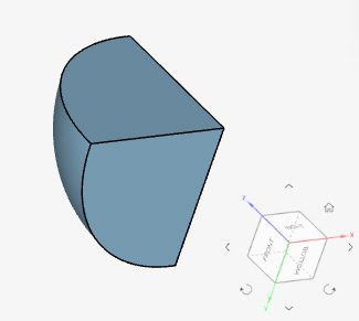
The result is a quarter of a sphere.
Subtract
The Subtract operation can be used for the following operations:
- To remove the common volume from one of the entities while keeping it intact in the other
- To remove the common volume along with one of the entities
The settings panel for this operation is shown below:
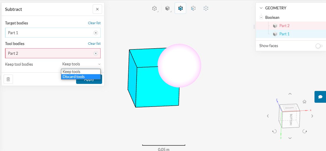
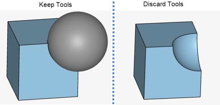
The settings panel asks the user to select target bodies and tool bodies. A target body is a body to subtract from while a tool body is a body to be subtracted. In this example, we choose to subtract the sphere (in pink) from the cube (in blue).
One more important step is to choose whether to keep the tool bodies or not. If Keep tools is selected then the common volume gets subtracted only from the target body. The final result still has two separate bodies.
If Discard tools is selected then both the common volume and the tool body gets subtracted. The final result now has a single body. Both the results are shown in the figure below:
Transform
Under this section, there are operations that allow users to move the part volumes within their geometry by either translating them whole up to a certain distance or rotating them by a specified angle.
Translate
As the name suggests, the Translate feature aids in translating the body or bodies up to a certain specified distance in the specified directions. Similar to the Move operation, there are two methods to proceed:
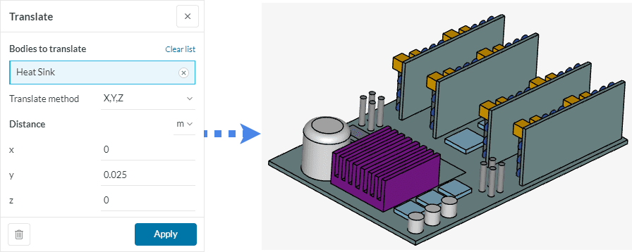
X, Y, Z
With this method, you can specify the distance up to which the selected volume needs to be translated in each direction. A negative value would translate in the opposite direction. Kindly follow the orientation cube at the bottom right to avoid confusion.
Following the same example from Figure 9, this time instead of moving the face of the heat sink we will move the whole heat sink body in the positive y-axis by a distance of 0.025 \(m\).
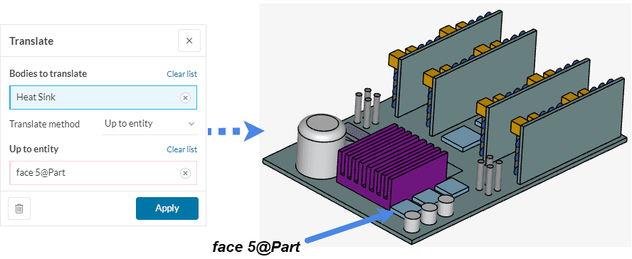
Up to Entity
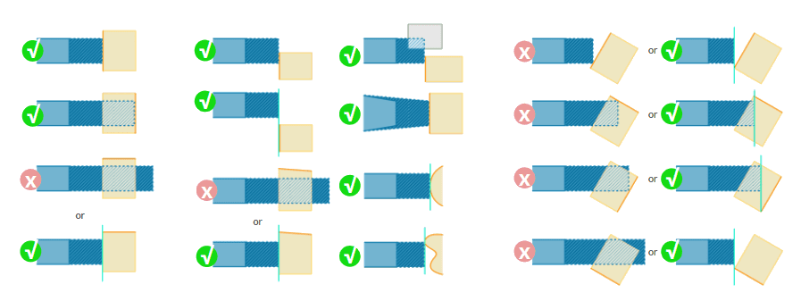
In this method, you just have to assign the face of the entity up to which the assigned volume needs to be translated. This time we assigned a face of the chip for the algorithm to translate the heat sink such that its foremost face is coplanar with that of the chip.
The following schematic perfectly represents the possibilities of a successful up to entity translate operation:
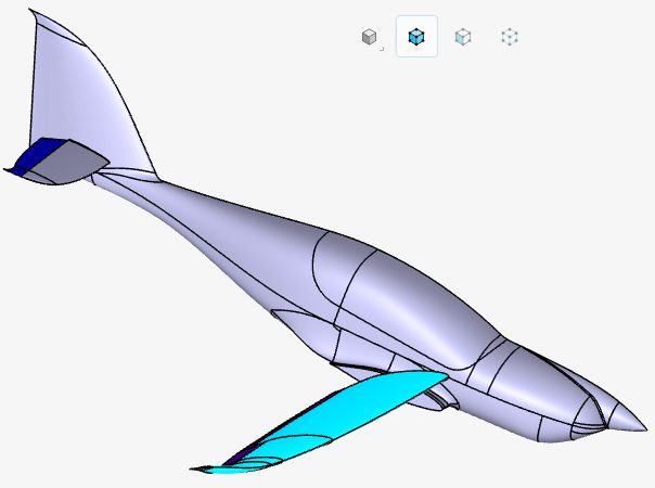
Rotate
As the name suggests, the Rotate feature aids in rotating a body or multiple bodies about a specified axis. This axis of rotation passes through the center of an imaginary bounding box whose dimensions represent the minimum and maximum coordinates of that body (or bodies combined) in the x-, y-, and z-direction.
Let’s look at the following example:
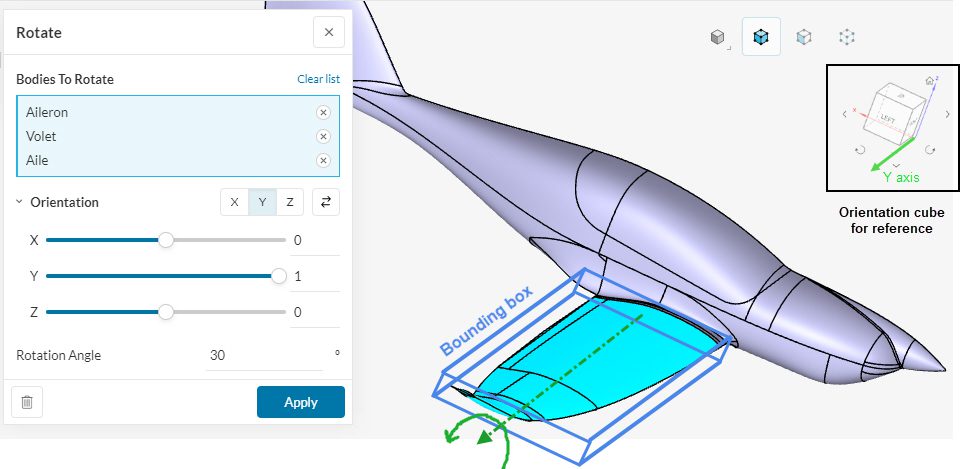
Here, different parts of the airplane wing are being rotated about the positive y-axis. This means that all these parts will rotate, in the anti-clockwise direction, at the same time about the central axis of the bounding box pointing in the positive y-direction. It is advised to refer to the orientation cube while assigning the rotation axis. Clicking on the inverse button ![]() will result in the reversal of the axis assigned (negative y-axis in this example).
will result in the reversal of the axis assigned (negative y-axis in this example).
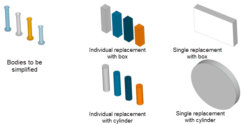
Simplify
Often there are instances where the CAD model has too much detailing that is insignificant from the simulation point of view. This may include threads on a bolt or pattern imprint on a tire. These fine details can cause simulation overhead by requiring a fine mesh and subsequently a high consumption of core hours.
With the Simplify feature, these fine details can be replaced with primitive shapes like cylinders or boxes that occupy minimum bounding dimensions.
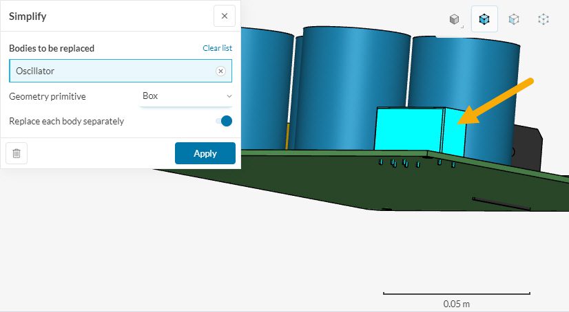
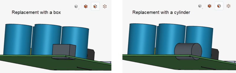
Multiple bodies can be replaced in a single operation either with a cylinder or a box. By default each body is replaced separately however this can be toggled off to generate a single resultant body.
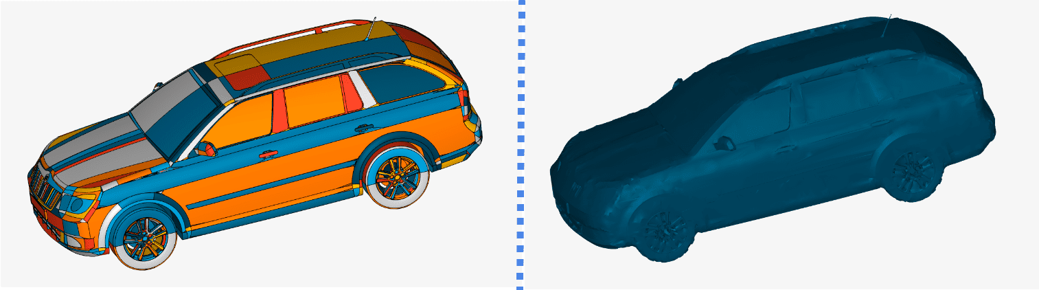
Wrap
The Wrap Surface operation is intended to generate a simulation-ready CAD model in situations where it contains a lot of artifacts like self-intersections, holes, cracks, overlaps, unimportant features, etc. Cleanup of such CAD can be very complex and extremely time-consuming, often even impossible, making it unsuitable for meshing.
The settings look as follows:
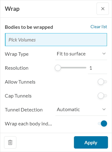
- Bodies to be wrapped: Whole CAD model or a part of the model to be used as an input to the wrapping procedure.
- Wrap Type:
- Fit to surface: This will try to make a wrap closest to the original body, however, it will not make any attempts to preserve any features like sharp edges. This operation is more robust and stable.
- Snap to edges: This will try to fit the resulting surface to sharp edges in the model. Sharp edges are currently defined as edges on the geometry where the angle between adjacent surfaces is larger than 30°.
- Resolution: This controls the wrap precision. Values between 1 and 10 are accepted. Higher values produce geometry that closely represents the input surface. Lower values result in a faster, but coarser representation.
- Allow Tunnels: If toggled on, it will allow the result to be topologically more complex than a sphere. This means tunnels or even multiple disconnected surfaces.
- Cap Tunnels: If toggled on, the algorithm will try to close all detected tunnels, pockets, and gaps, simplify the model, and create an outside envelope while still maintaining other significant features.
- Tunnel Detection:
- Automatic: Detects the tunnels automatically.
- Manual: Requires the minimum tunnel diameter that is needed to be recognized.
- Wrap each body individually: An option to wrap all selected bodies at once as a group or wrap each selected body individually.
Model
Fix Interferences
Fix interferences should be your option when trying to fix the interfering bodies in your CAD model automatically. Just click on the icon and hit ‘Apply’. It should get rid of all the interfering parts. Users should note that, in this automatic operation, the smaller body is subtracted from the larger body.
Don’t forget to run an interference check again just to be certain (see Interferences below). You should see a “No Interferences found in your CAD Model” message.
Add CAD
The Add CAD operation allows you to add parts to an existing CAD model in SimScale. As an example, the Electronics Box geometry below is missing one Large Capacitor:
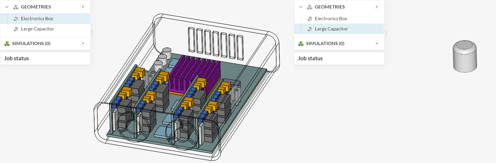
In CAD mode, you can create a new ‘Add CAD’ operation to have both CAD models combined:
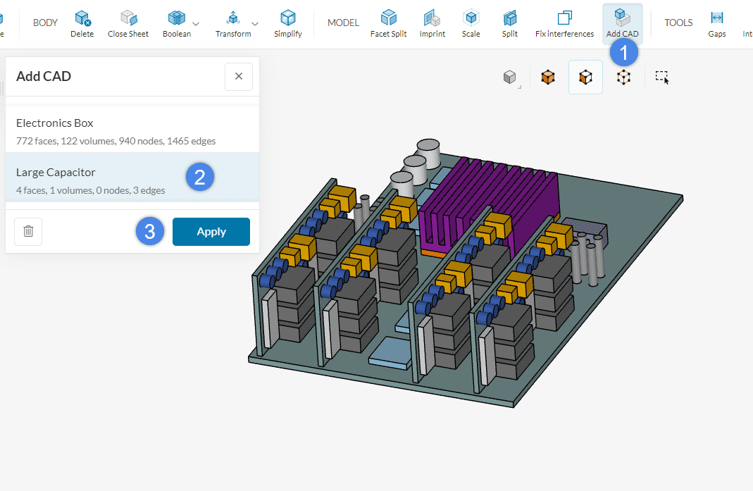
As a result of the operation, the capacitor is added to the electronics box geometry:
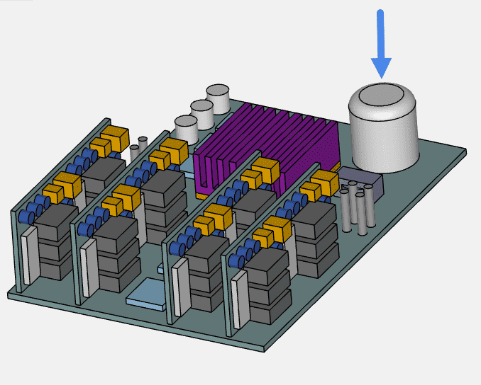
It is worth noting that the new CAD part is added respecting its original coordinates. If the new part needs to be re-positioned, please consider using a translate CAD edit operation.
Create
Flow Volume
A CFD simulation is performed on the actual fluid volume. For an internal flow problem, this means that the fluid volume needs to be extracted from the CAD geometry or, be created around the CAD geometry for an external flow problem.
This can be performed in the CAD editor using the Flow volume operation. More information on flow volume extraction can be found here.
External Flow Volume
To create an external flow volume, you need to enter the minimum and maximum dimensions for the volume in the x-, y-, and z-direction. Optionally, select a seed face that corresponds to any face on the CAD geometry.
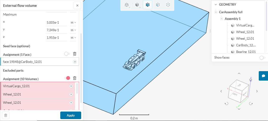
By default, this operation retains all the CAD parts. You can specifically exclude them by selecting them under Excluded parts. If unsure, the parts can also be deleted later using the delete operation for the body (discussed above).
Internal Flow Volume
To create an internal flow volume you need to specify a seed face and one or more boundary faces ( lies between the external environment and the internal).
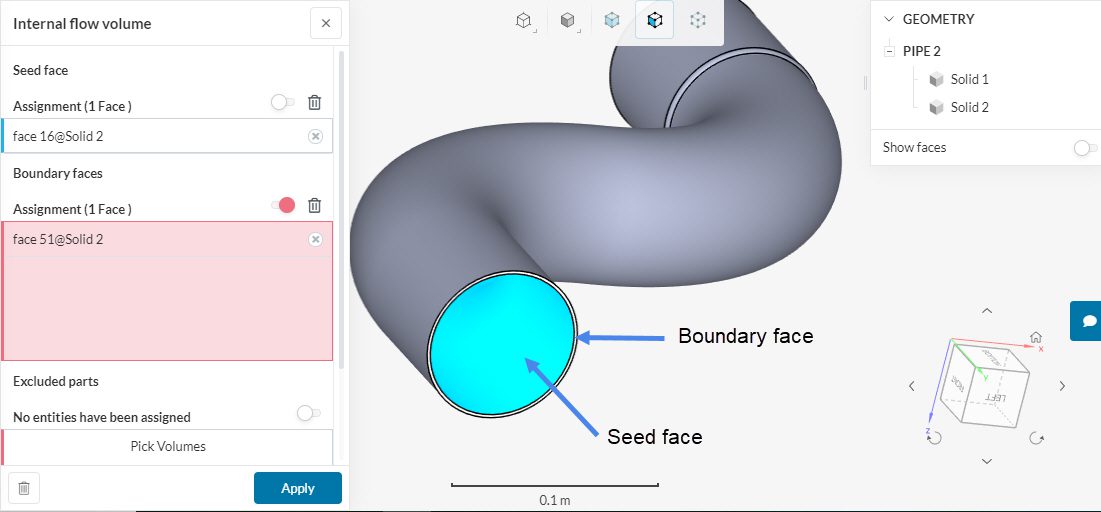
Similar to external FVE internal FVE also retains all the CAD parts. You can exclude them under Exclude parts option.
Important
Users should note that faces selected for operation in a flow volume extraction process, such as seed face and boundary face, cannot belong to the excluded parts (volumes) of the CAD model.
Internal Caps
The Internal caps operation creates cap faces for the inlets and outlets of the internal flow domain and groups them into a sheet body. The operation can currently only be used with the Immersed Boundary analysis type. Internal caps operation creates faces (caps) that cover the inlets and outlets of the internal flow volume. The faces can later be used for the definition of boundary conditions. Read more about this operation here.
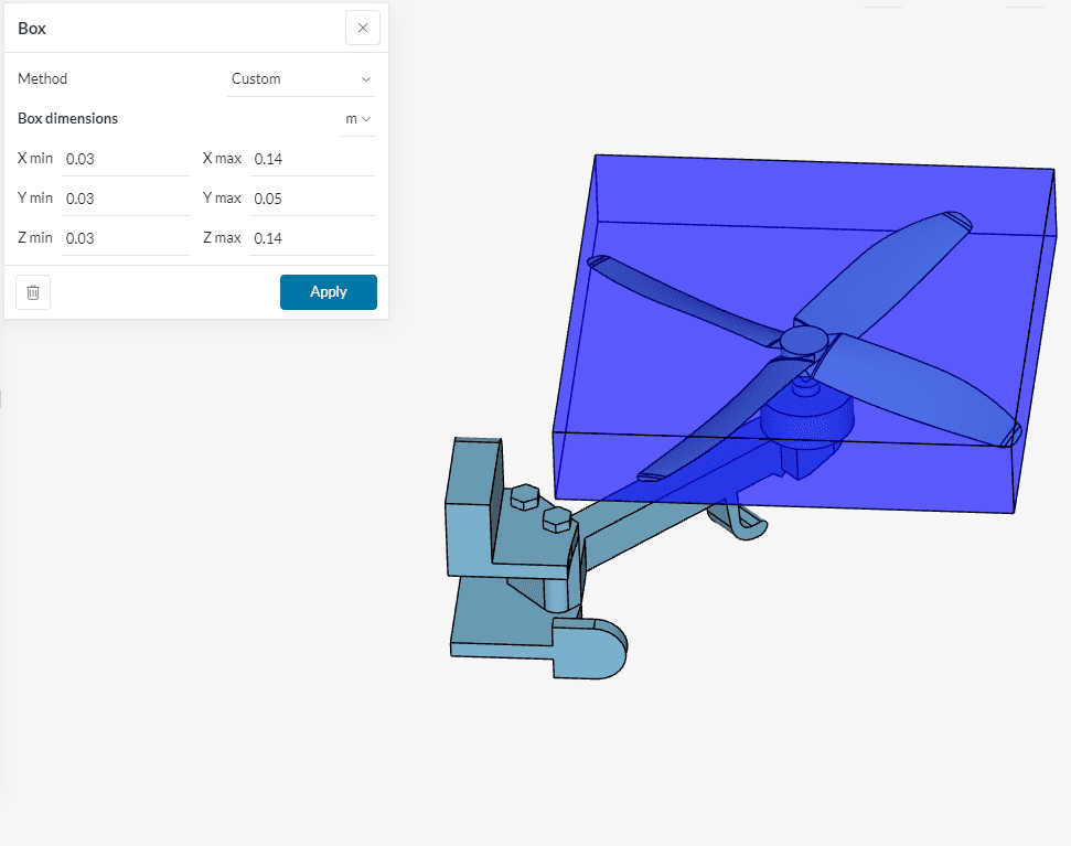
Box
By clicking Box, the user is allowed to create a box shape within CAD Edit. This is particularly helpful in manually creating internal or external flow volumes by a subsequent Boolean Subtraction, if the Create → Flow Volume option does not work.
There are two methods to create boxes: Custom and From faces.
When using the Custom method, the box’s X, Y and Z min/max coordinates need to be specified by the user.
As this might be a cumbersome process when one does not know the exact global coordinates to be applied, another option is to select faces which will be covered by the box, as shown in the picture below.
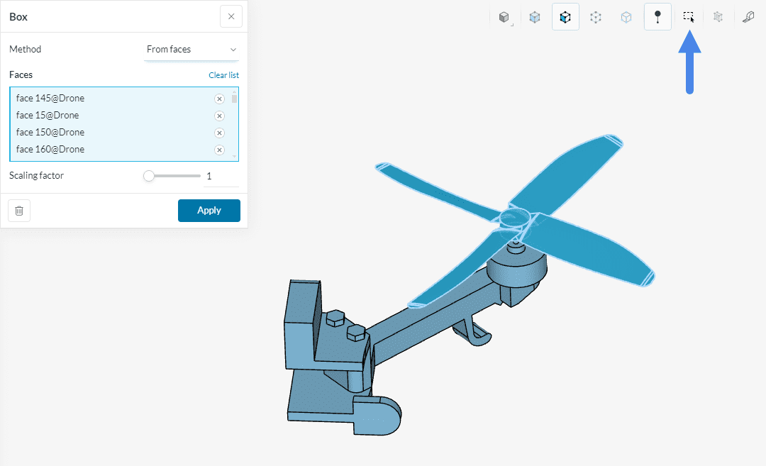
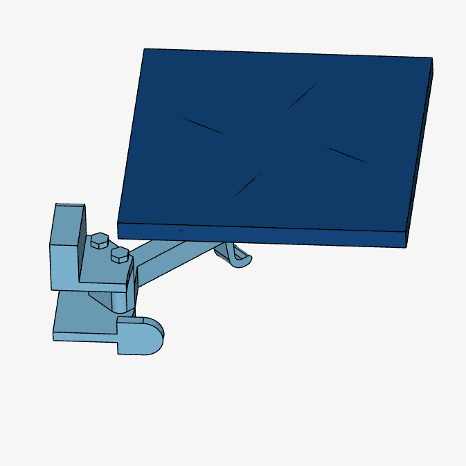
A Scaling factor may also be used in case one wants a box to envelop a higher volume than the one delimited by the chosen faces. The result of this operation is depicted in the picture below.
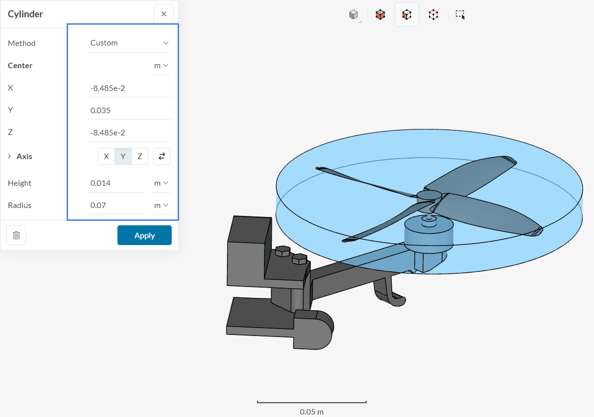
Cylinder
This operation allows the creation of a cylinder, which is especially useful in simulations involving rotating zones. There are two methods to create cylinders: Custom and From faces.
When using the Custom method, the center of rotation, axis of rotation, radius, and height of the cylinder need to be specified by the user.
The Custom approach requires global coordinates to be provided for the creation of the cylinder. In case you don’t have those readily available, the From faces approach might be preferred.
When using the From faces approach to create a cylinder, the user needs to select the Faces which should be covered by the cylinder:
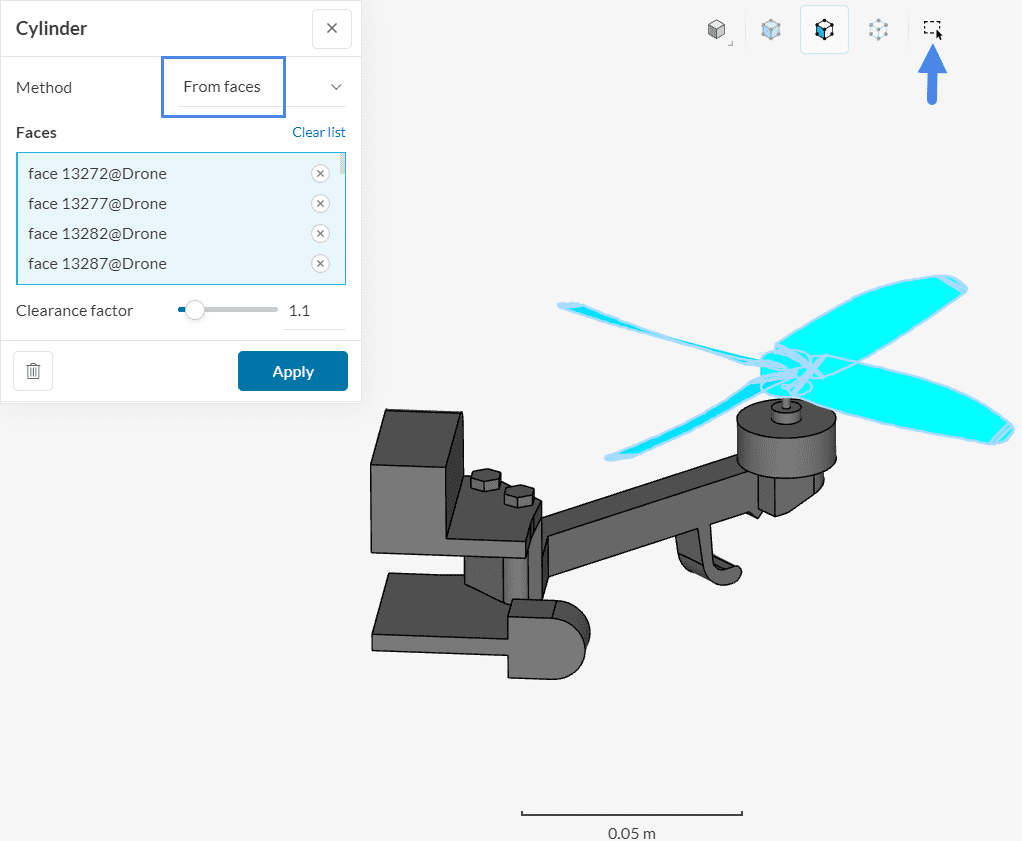
With this approach, a cylinder that envelops all selected faces is created. Furthermore, a Clearance factor is applied, ensuring that the cylinder is slightly larger than the assigned faces. For simulations involving rotating machinery, a Clearance factor of 1.1 is recommended.
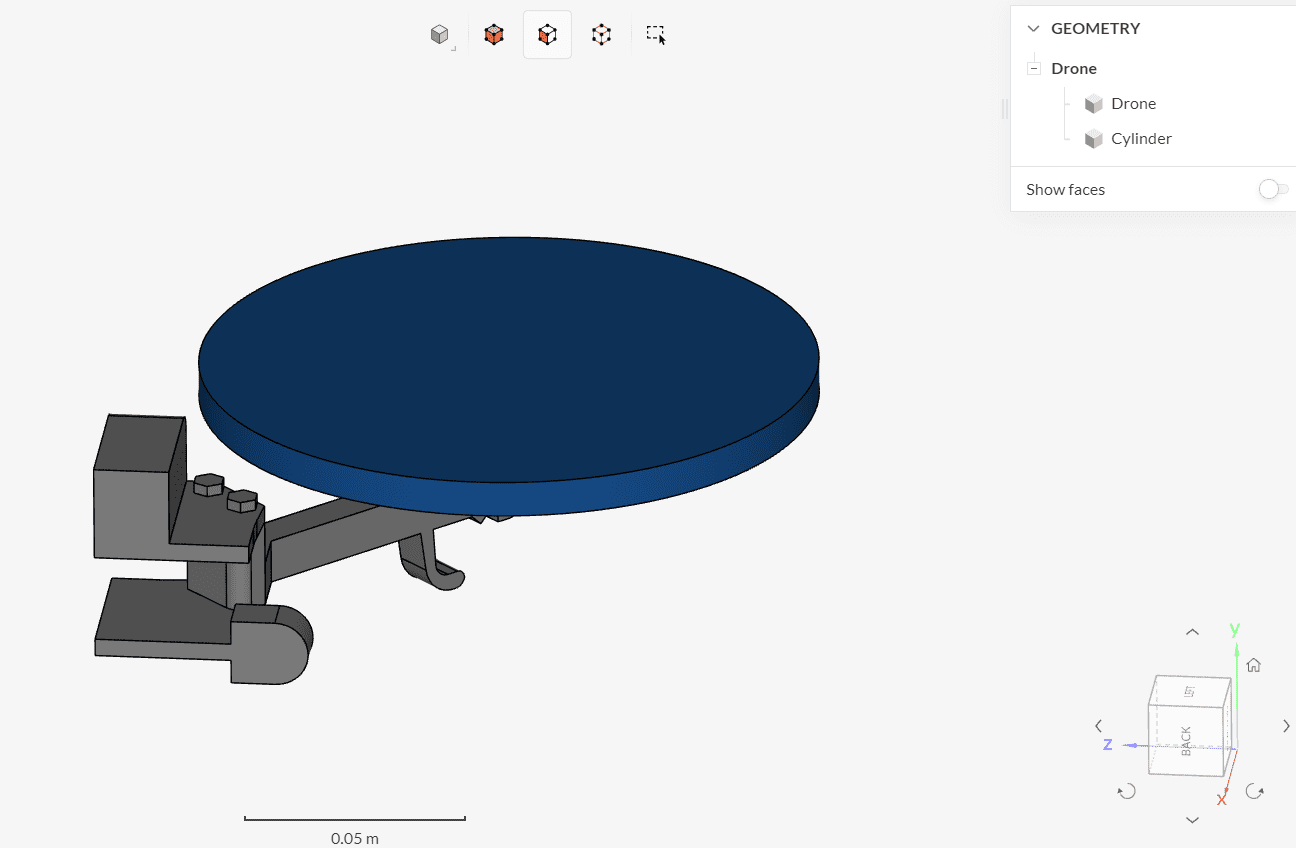
As a result of the Cylinder operation, a brand new volume is created:
Tools
Interferences
Your CAD model is not ready for the simulation setup if it has interfering solid parts. Interfering/Overlapping solid parts can result in the failure of geometry operations performed while editing the geometry and more importantly cause the meshing algorithm to fail. Hence, it should be avoided at all costs.
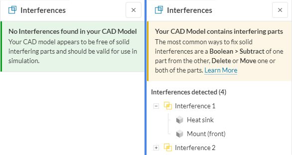
To check for interfering parts click on the ‘Interference’ icon and wait for a message while the operation runs in the background. A valid CAD model with no interfering parts should display the message on the left as shown below:
To fix interferences manually use boolean or delete-body operations described above. Additionally, for automatic fixing of interferences use the Fix interferences feature discussed under Models.
Gaps
When preparing your CAD model there are often undesired gaps that are not visible or overseen and can lead to mesh quality issues or prolonged run times. These gaps need to be identified and fixed at an early stage. For example, in a CHT case, all the components must be in contact with each other to capture the heat transfer correctly. The below geometry has thin gaps because of which contact cannot be generated between the mainboard and the chip.
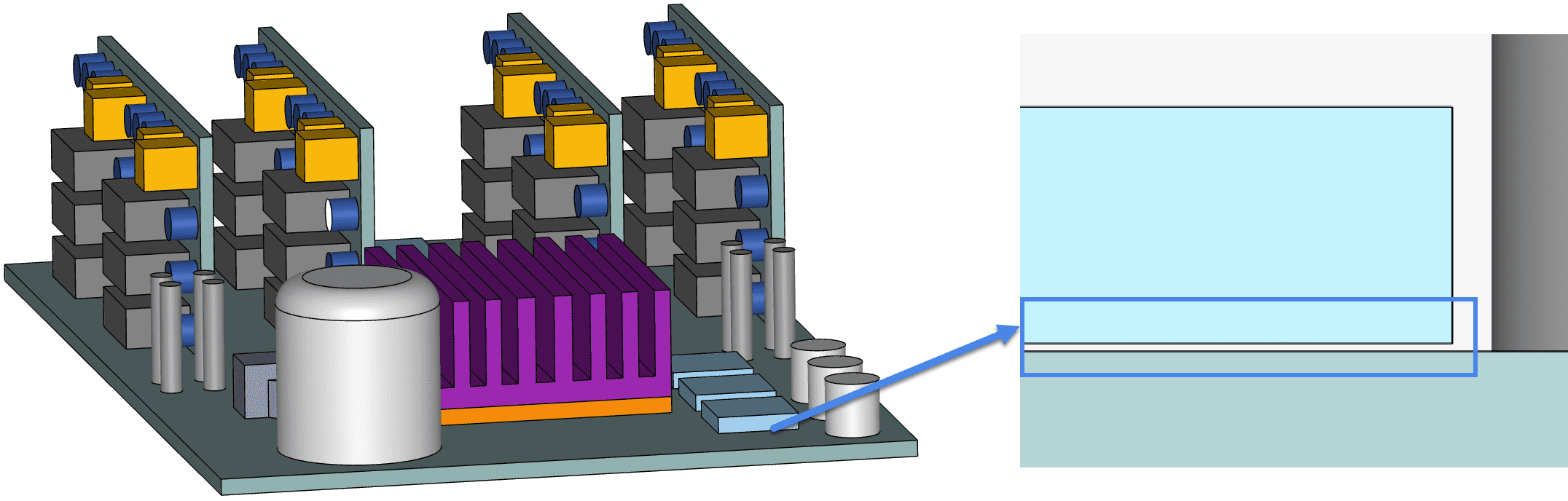
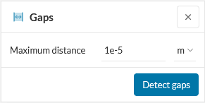
To detect these small gaps click on the ‘Gaps’ icon and then specify the ‘Maximum distance’ to define a gap tolerance and then hit ‘Detect gaps’. All gaps that are equal to or less than the maximum distance will be detected. Depending on the CAD model this can take a while and will display a message as shown in the below figure.
After running the operation, the following results can occur, depending on the Maximum distance:
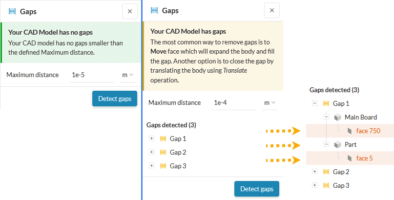
Upon expanding the detected gaps and selecting a face, the corresponding face will be highlighted in red color on the model. These gaps can be fixed either via Move>Face or Translate operations.
Last updated: May 19th, 2026
Did this article solve your issue?
How can we do better?
We appreciate and value your feedback.


