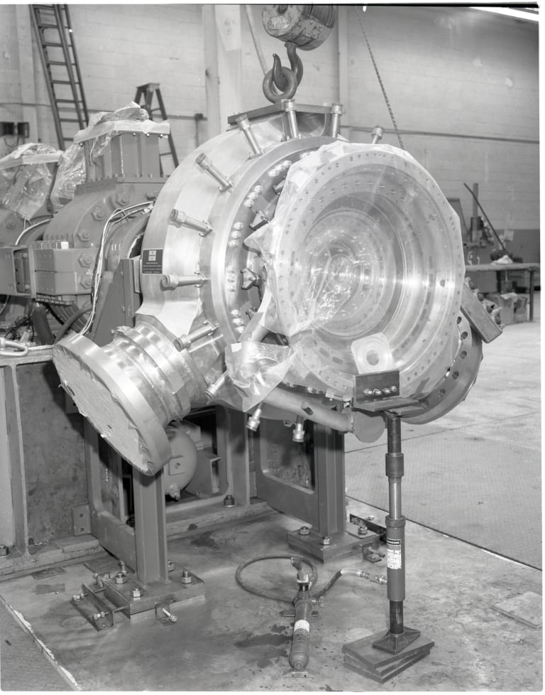
A water turbine, with the Kaplan, Pelton, and Francis turbines being the most common ones, is a large rotary machine that works to convert kinetic and potential energy into hydroelectricity. These modern equivalents of the water wheel have been used for over 135 years for industrial power generation, and more recently hydropower energy generation.
Francis Turbine What Are Water Turbines Used for Today?
Today, hydropower contributes to 16% of the world’s power generation. In the 19th century, water turbines were predominantly used for industrial power before electrical grids became widespread. Currently, they are used for electric power generation and can be found in dams or areas where heavy water flow occurs.
With global energy demand rising rapidly and factors such as climate change and depleting fossil fuels, hydroelectricity has the potential to make a large impact as a form of green energy on a worldwide scale. As the search for environmentally friendly and clean power sources continues, Francis turbines could prove to be a very popular and increasingly adopted solution in the coming years.
Francis Turbine How Do Water Turbines Generate Electricity?
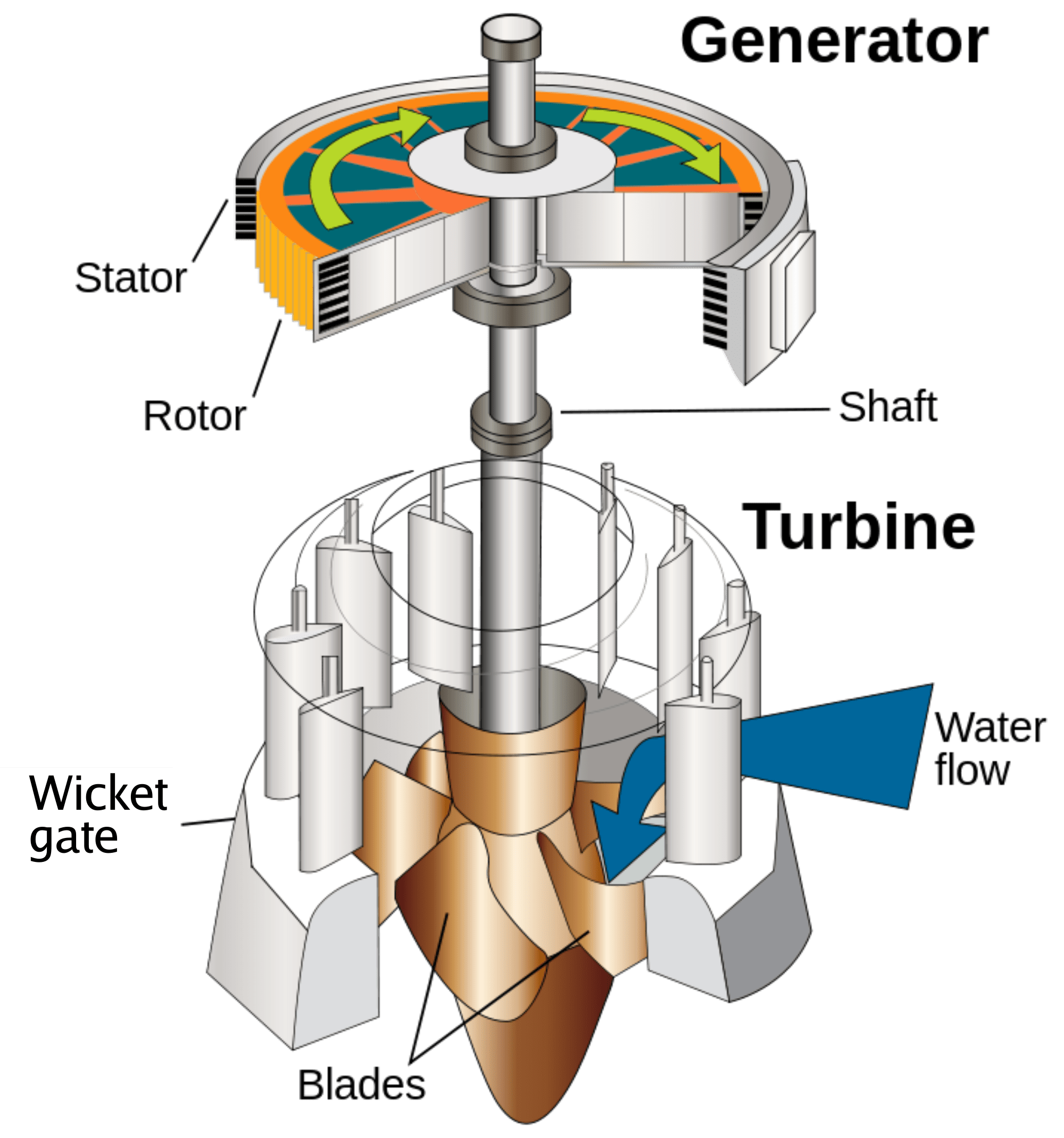
Water pressure created from naturally or artificially flowing water exists as the energy source for water turbines. This energy is captured and turned into hydroelectric power. A hydropower plant will generally use a dam on an active river to store water. The water is then released in increments, flowing through the turbine, rotating it, and activating a generator that then produces electricity.
Francis Turbine How Big Are Water Turbines?
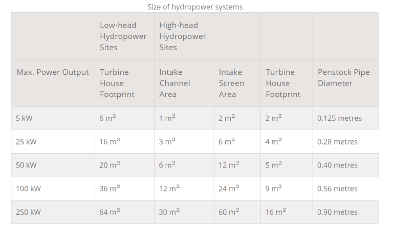
Based on the head under which they operate, water turbines can be classified into high, medium, and low head. Low-head hydropower systems are larger, as the water turbine has to be large to achieve a high flow rate while low water pressure is applied across the blades. In turn, high-head hydropower systems don’t need such a large surface circumference, as they are used to harness energy from faster-moving water sources.
Below, we will explain a few examples of different types of water turbines used for different applications and water pressure.
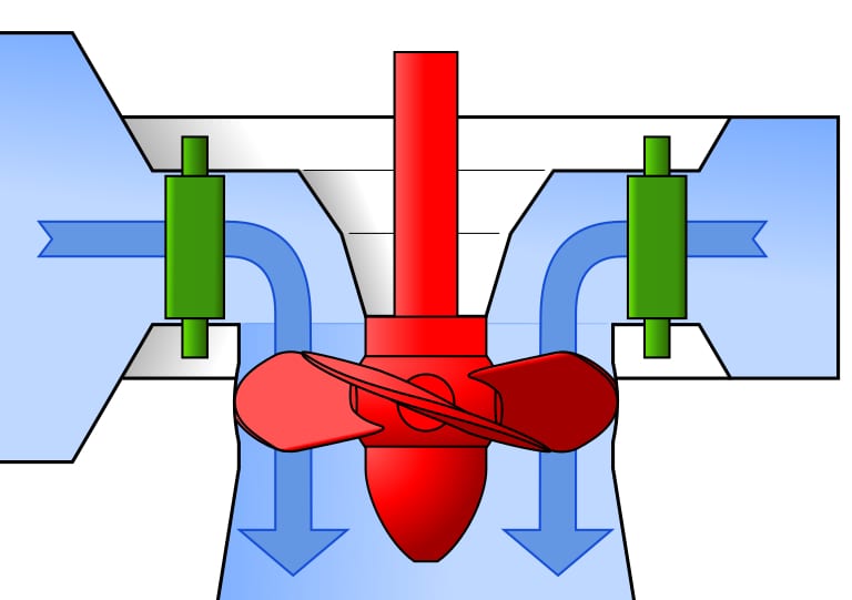
Kaplan Turbine (0-60m Pressure Head)
These turbines are known as axial flow reaction turbines, as they change the pressure of the water as it flows through it. The Kaplan turbine resembles a propeller and features adjustable blades to maximize efficiency over a range of water and pressure levels.
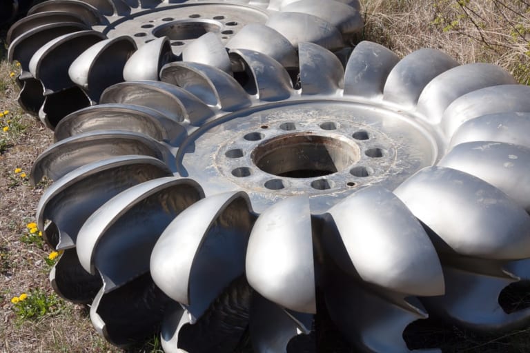
Pelton Turbine (300m-1600m Pressure head)
The Pelton turbine—or Pelton wheel—is known as an impulse turbine, as one that extracts energy from moving water. This turbine is suited for high head applications, as it requires a high amount of water pressure to apply force on the spoon-shaped buckets, and cause the disk to rotate and generate power.
Francis Turbine (60m-300m Pressure Head)
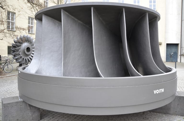
The final and most famous water turbine, the Francis turbine, accounts for 60% of the world’s hydropower. Working as an impact and reaction turbine that operates at a medium head, the Francis turbine combines axial and radial flow concepts. By doing this, the turbine fills the gap between high and low-head turbines, creating a more efficient design, and challenging engineers today to further improve upon it.
More specifically, a Francis turbine operates by water flowing through a spiral casing into (static) guide vanes which control the flow of the water towards the (moving) runner blades. Water forces the runner to rotate through the combined impact and reaction of forces, finally exiting the runner through a draft tube that discharges the water flow into the external environment.
Turbine Design How Do I Choose a Water Turbine Design?
Choosing the optimal turbine design often comes down to one thing; the amount of head and flow rate accessible to you. Once you’ve established what kind of water pressure you can harness, you can then decide if an enclosed “reaction turbine design” like the Francis turbine or an open “impulse turbine design”, like the Pelton turbine is a better fit.
Finally, you can establish the necessary speed of rotation of your proposed electrical generator.
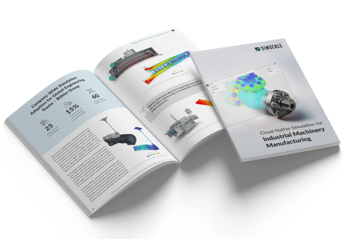
Cloud-Native Simulation for Industrial Machinery Manufacturing
Our latest eBook explores how cloud-native simulation is transforming industrial machinery manufacturing challenges into opportunities. Download it for free by clicking the button below.
Francis Turbine How Can You Optimize Your Water Turbine Design with CFD?
Once you’ve decided upon the turbine design that suits your resources and meets your power needs, simulating your CAD on an online platform like SimScale allows you to further optimize your design by simulating in 3 easy steps; uploading your CAD, setting up your simulation, and making design decisions based on your findings.
Using fluid flow (CFD) simulation in particular allows you to explore the localized conditions. Along with this, CFD simulation lets you hone in on and analyze parameters including flow rate, pressure drop, efficiency, unexpected turbulence and unwanted vapor pressure. For a detailed video and case study of how you can use CFD to improve your Francis turbine design, watch the webinar below, and follow along with these slides.
Francis Turbine Case Study: Francis Turbine Design Optimization
The project used for this case study can be freely accessed in the SimScale Public Projects Library. The above webinar’s demonstration evaluated the following factors:
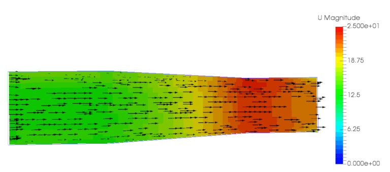
Francis Turbine Flow Through the Inlet Duct
The simulation tested the velocity within the inlet duct, with the goal of accelerating the water flow in this converging passing area to improve the design’s efficiency. The simulation revealed that the flow could be accelerated.
Francis Turbine Flow Through the Casing
Assessing the flow through the casing is also of interest, as maintaining a constant velocity and having a circumferentially uniform pressure to the runner blades is ideal. Maintaining the velocity is a difficult design challenge, but it is important. As an impeller pump, the flow needs to enter the impeller evenly throughout the entire circumference. The simulation found that in the initial design, this aspect could be improved upon.
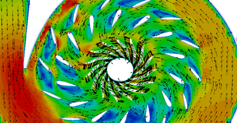
Francis Turbine Flow Around the Turbine Blades
Evaluating the flow around the blades is imperative to decrease recirculation, which expends energy that could have been extracted for power. The simulation found that this appeared to be the case in the initial turbine design.

Francis Turbine Static Pressure on the Blades
Assessing the static pressure on the turbine blades is also important. It must be guaranteed that the fluid vapor pressure is never reached and that cavitation is avoided. It is critical to be able to guarantee the life of the turbine. The simulation found that the blade design could be improved upon to further prevent the risk of causing cavitation.

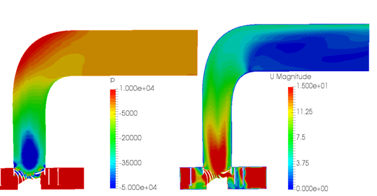
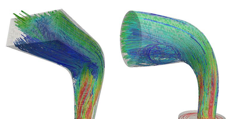
Francis Turbine Flow Through the Draft Tube
The draft tube decelerates the fluid from the exit of the runner to the discharge to increase pressure and minimizes the loss of kinetic energy. The simulation found that the design could be improved upon to make this change more gradual to save energy. This aspect of the design was then chosen for optimization.
Francis Turbine Results: Modified Draft Tube & Stator Angles
Through modification of the stator angles, it was then demonstrated how recirculation can be improved or worsened by altering certain elements based on what the simulation has highlighted. At the same time, the draft tube modification leaves the high to low-pressure change more gradual, thereby optimizing the system.
Francis Turbine Performance Increase
The implemented design modifications led to an increase of 1.5% in the peak efficiency of the Francis turbine, to an additional 450 kWh of energy.
Clearly, there is more gain here. Optimizing two things together is never sensible. The next step would be to understand the impact of the draft tube modification alone, then to optimize the stator separately.
Francis Turbine Conclusion
Simulating your water turbine design with CFD will help you learn how to improve your design’s performance, maximize energy capture from your water source, and increase the lifespan of your turbines. Discover Designcraft’s success story to read more.


