Connectors
Connectors help to reduce the complexity of a multipart structural analysis. This is achieved by defining the connection between multiple parts, without the need for a physical component.
Connectors are supported in the following structural simulation types:
- Static
- Dynamic
- Thermomechanical (only pin connectors)
- Harmonic
- Frequency Analysis
The following connectors are available within SimScale
- Pin connectors
- Bolt connectors
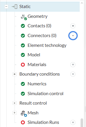
A new connector can be created by clicking the ‘+’ icon in the simulation tree as shown in Figure 1.
Large Displacements
Please be aware that SimScale only allows for small displacements within the connectors. For larger displacements or rotations it is necessary to use physical contacts, between all parts of a connection, including the connecting part.
Pin Connectors
Pin connectors allow the user to replace a physical pin within an assembly with a virtual connection using a combination of kinematic relations and 1D finite elements. The virtual connection mimics the physical behavior of the pin and avoids the need for finely meshed physical parts and complex contact setups.
Important
Usage – Pin connectors
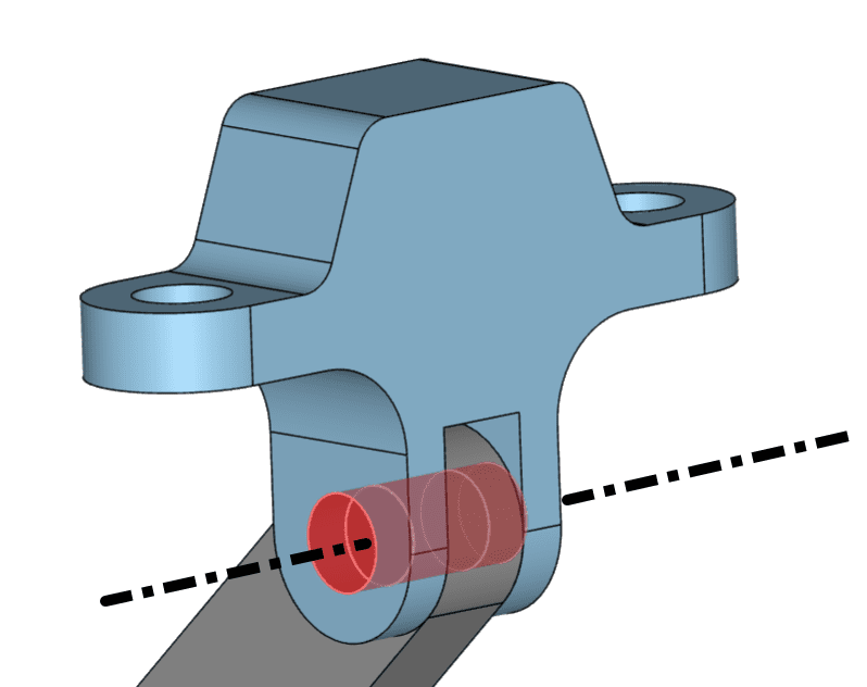
A pin connector can connect multiple bodies around a shared pin axis and the kinematic behavior of the connection can be defined with the settings as shown in Figure 3. This is known as a body to body connection and in this case, the virtual pin will move with the deformation of the bodies.
Alternatively, a pin connector can be used to connect bodies to a pin that is fixed to the ground and this is known as a body to ground connection. Here the virtual pin remains stationary and the connection acts as a global constraint.
The default settings panel for the pin connectors can be seen in Figure 3.
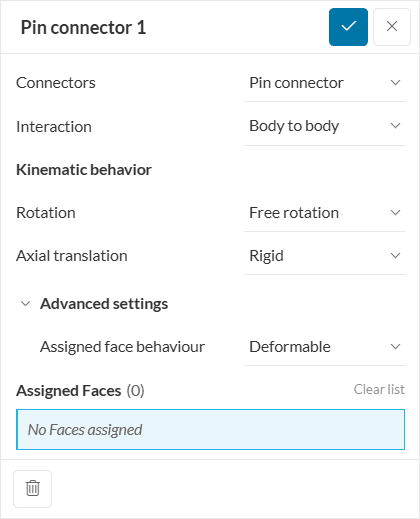
The settings are explained as follows:
- Interaction
- Body to body: Two or more bodies may be connected to each other via a single virtual pin. The pin will move with the bodies.
- Body to ground: Two or more bodies may be connected to the ground via a single virtual pin. The pin remains stationary.
- Kinematic Behavior
- Rotation
- Free rotation: Bodies may freely rotate about the pin axis
- Rigid: Rotation of the bodies about the pin axis direction is locked
- With torsion spring: Rotation is controlled by a torsion spring stiffness
- Rotation
- Axial translation
- Rigid: Translation of the bodies in the pin axis direction is locked
- Free sliding: Bodies may freely translate along the pin axis
- With axial spring: Define an axial spring stiffness for axial movement
- Advanced Settings
- Deformable: Allows for small deformation of the assigned faces
- Undeformable: Allows for no deformation of the assigned faces
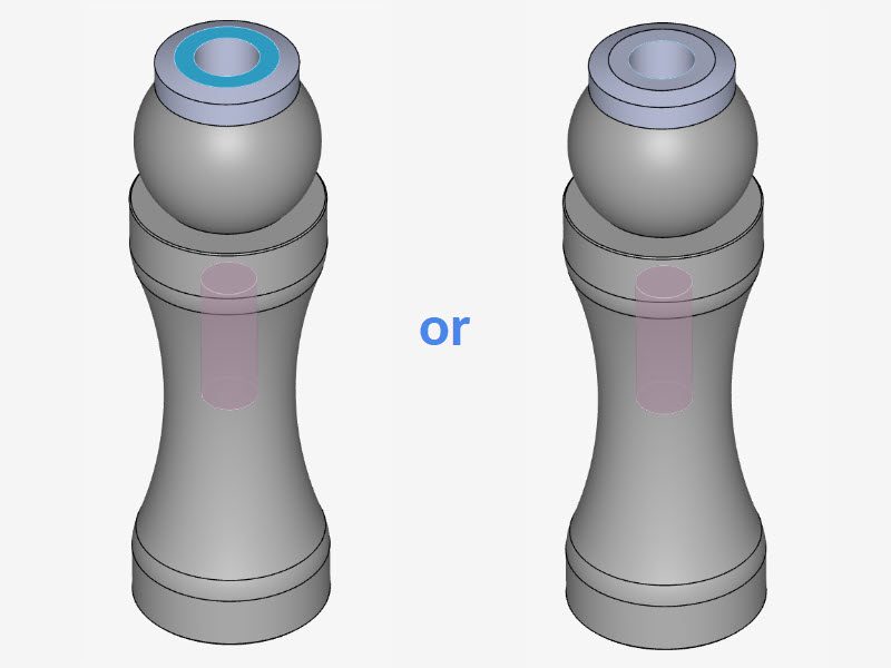
Assigning Pin Connector Faces
When assigning the faces of a pin connector please ensure that the faces are concentric. This means that the faces need to share the same rotational axis. If this condition isn’t fulfilled the simulation will result in an error warning.
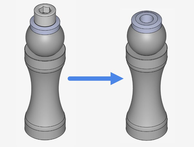
Bolt Connectors
Similar to the pin connectors, bolt connectors are also virtual and make it possible to simulate physical bolts via their replacement by a mathematically equivalent model.
Important
Usage – Bolt connectors
A bolt connector can replace the physically restrained connection of multiple bodies. There are two types of bolts, namely, Bolt and nut and Screw. Figure 6 highlights the default settings for these kinds of connectors as they appear in the Workbench.
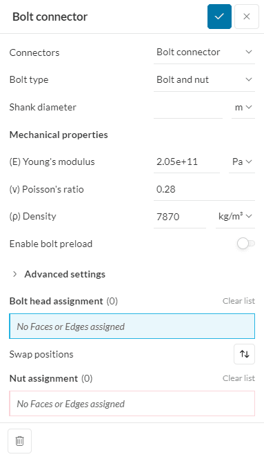
The settings are explained as follows:
- Bolt type
- Bolt and nut: Replaces a bolt and nut physical connection. Needs one or more surfaces/edges for the bolt and one or more for the nut face. Surfaces/edges must belong to the same body.
- Screw: Replaces a screw real connection. Needs one or more surfaces/edges for the bolt’s head and one or more cylindrical surfaces for the threaded face.
- Shank diameter: Diameter of the bolt’s shank
- Mechanical properties: For more information, take a look at this page.
- (E) Young’s Modulus
- (v) Poisson’s Ratio
- (\(\rho\)) Density
- Enable bolt preload: if there’s a preload applied to the bolt, toggle to on. Then, a Force value will be required.
- Advanced settings
- Assigned face behaviour
- Deformable: Allows for small deformation of the assigned faces
- Undeformable: Allows for no deformation of the assigned faces
- Assigned face behaviour
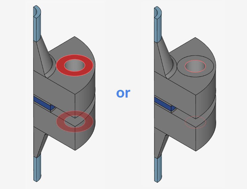
Assigning Bolt Connector Faces/Edges
When assigning the faces of a bolt connector please ensure that the faces/edges are concentric. This means that the faces need to share the same rotational axis. If this condition isn’t fulfilled the simulation will result in an error warning.
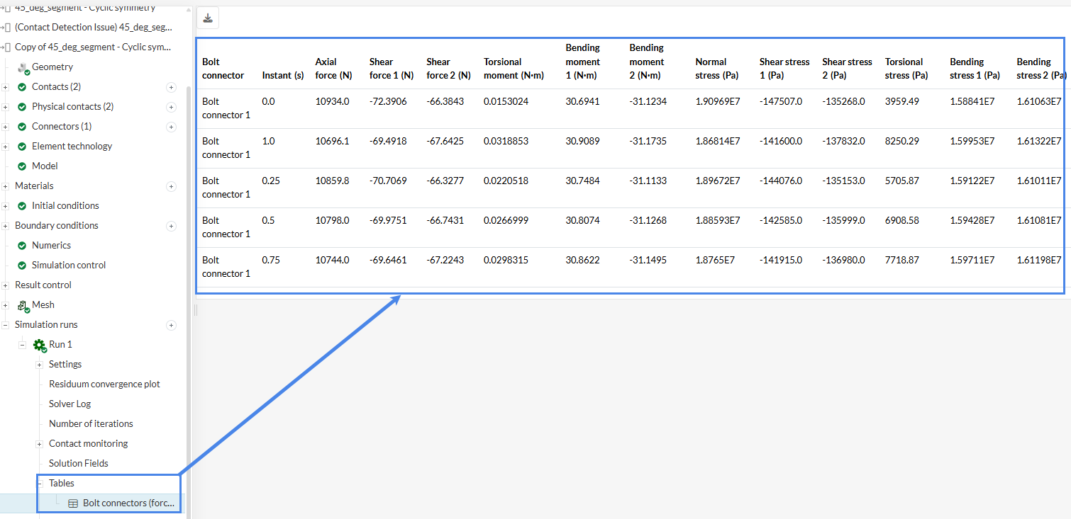
Bolt Connectors (Forces and Stresses)
Upon completing a simulation that includes bolt connectors, SimScale generates a detailed results table. This table provides a consolidated overview of the mechanical response of each bolt, including forces transmitted through the connector and corresponding stress values. This enables a quick assessment of bolt behavior under load, the identification of overstressed fasteners, and performance comparisons across the assembly. The variables included in this summary are:
- Axial force (\(N\))
- Shear force (\(N\))
- Torsional moment (\(N \cdot m\))
- Bending moment (\(N \cdot m\))
- Normal stress (\(Pa\))
- Shear stress (\(Pa\))
- Torsional stress (\(Pa\))
- Bending stress (\(Pa\))
The table reports some variables as two separate values, such as ‘Shear Force 1’ and ‘Shear Force 2’. This occurs because the software outputs bolt forces using a Local Coordinate System (LCS) rather than the global coordinate system. Using an LCS ensures that, regardless of the bolt orientation in 3D space, the reported forces always align with the physical axis of the bolt. For each bolt connector, the software defines three orthogonal axes to fully describe the loading condition:
- Axial Direction: This axis aligns with the longitudinal centerline of the bolt shank.
- Shear Plane: The remaining two axes are perpendicular to the bolt shank and to each other. Together, they define the cross-sectional shear plane where shear occurs. Consequently, shear force is reported as two components, with each value corresponding to shear acting along one of these perpendicular directions.
Last updated: February 17th, 2026
Did this article solve your issue?
How can we do better?
We appreciate and value your feedback.


