Contacts in Conjugate Heat Transfer
In a Conjugate Heat Transfer (CHT) analysis, an interface defines the physical behavior between the common boundaries of two regions that are in contact, e.g. solid-solid, or solid-fluid.
Important
In conjugate heat transfer simulations, all the fields at the interfaces are fully constrained by the Interface type. Therefore, defining boundary conditions to faces assigned to interfaces is not allowed. This would result in an overconstrained model.
If an interface is assigned to a boundary condition, the following error message is displayed when the user tries to start a simulation:
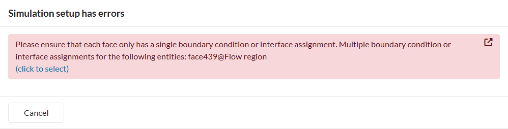
To solve this error, the user needs to unassign the interfaces from the boundary conditions.
Additionally, interfaces between two flow regions are not possible and will result in an error when running simulations.
Automatic Interface Detection
When creating a new CHT simulation, all possible interfaces will automatically be detected and populated in the simulation tree. Interfaces will be grouped together and defined as Coupled thermal interface.
How To Modify Specific Interfaces?
Individual interfaces or a group of interfaces can be filtered via entity selection. Select the entities (faces or volumes) for which you want to select all interfaces that exist between them.
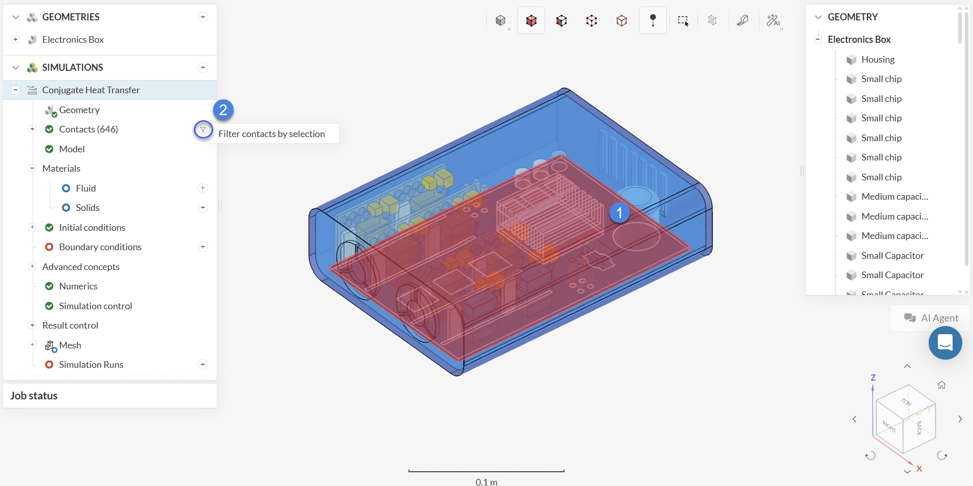
Once you filter the interfaces of interest, a window opens with additional options for the Interface type for the selected contacts.
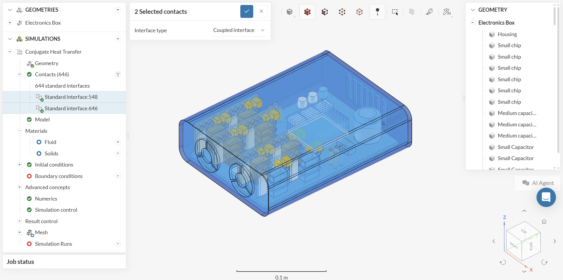
Interfaces which differ in settings from the standard bulk interfaces group will stay exposed individually in the simulation setup tree.
Contact Detection Errors
As all possible interfaces are detected automatically, it is not possible to manually add an interface or to change the entity assignment for a specific interface. In case no interfaces can be detected automatically, SimScale will show a warning message before running the simulation.
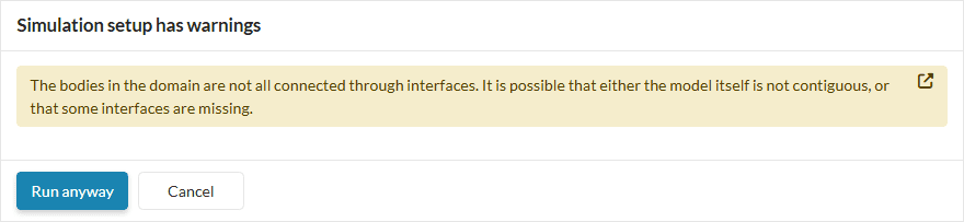
In this case, it is possible to create a mesh and start a simulation run for this simulation. However, it is recommended to investigate the CAD model for potential errors that prevent successful contact detection. Some common causes are:
Small gaps between the faces: If the face pair is separated by a gap higher than the CAD tolerance, the interface will not be detected. Sometimes, the gap is so small that it is difficult to find it by visual inspection. Please move the parts together or extrude the faces to create the proper contact.
Duplicate parts: Sometimes the CAD modeling history makes it so that parts can be duplicated upon export. Please check that such a condition is not present in your model.
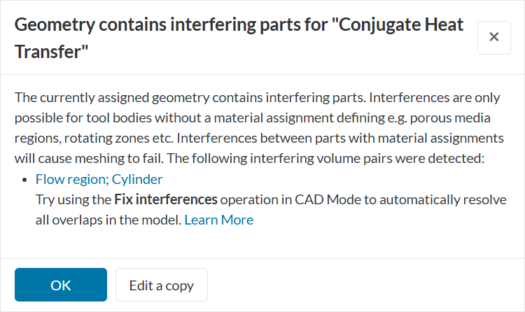
Interfering parts: If the face pair is intersecting into each other by a margin higher than the CAD tolerance, the contact will not be detected. Please move the parts away so that the faces are in perfect contact, or you can also perform a Boolean operation to create coincident faces. However, in the case the overlap is done on purpose because of the use of an advance concept, please ignore the warning and press OK.
Some of the fix operations described above can be performed in the CAD edit. If you are unable to complete the modifications using the operations available in the platform, proceed with your dedicated CAD software.
Interface Type
The Interface type options define the heat exchange conditions at the interface. The types available for the interfaces in CHT are reported below:
Coupled
The coupled thermal interface models a perfect heat transfer across the interface. This is the default setting, in case an interface is not defined by the user.
Thin Layer Resistance
The Thin layer resistance allows modeling a layer with thickness \(t\) and thermal conductivity \(\kappa\), and \(\rho\) electric resistivity between the two interface regions.
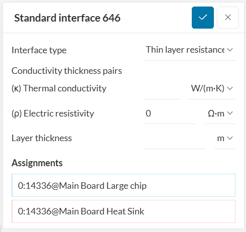
For example, it is possible to model the thermal paste between a chip and a heat sink without needing to resolve it in the geometry. Adding a thin layer to the geometry and meshing it is a problem, considering that the thickness of these layers is two or three orders of magnitude smaller than other components in the assembly.
When Joule heating is activated under global settings, it is important to take into account the electric properties at the contact surface. Electric resistivity (\(\rho\)) is a material property that quantifies how strongly a material opposes the flow of electric current. It depends on the material itself and is measured in Ohm-meters \([Ω·m]\).
Last updated: September 1st, 2025
Did this article solve your issue?
How can we do better?
We appreciate and value your feedback.


