The growth and improvement of many key industrial processes have always been linked to the improvements in the pumping equipment. Centrifugal pumps play a particularly important role because of their capacity to handle high flows. In fact, centrifugal pumps constitute more than 85% of the world’s production of pumps, as they are frequently used in sewage, food processing, water treatment and manufacturing plants, as well as the chemical and petroleum industries, where they are used for the pumping of all types of low-viscosity fluids. They can also easily handle liquids with high proportions of suspended solids present in them.
With the many varieties of available pump configurations, a proper design is the most important requirement for any facility. 20% of the total energy consumed globally is used to run a pump of one sort or another—yet, two-thirds of these pumps use 60% more energy than is required. To ensure energy efficiency and prevent equipment failure, it is important to be able to predict and evaluate the pump’s performance under different operating conditions. This is where computational fluid dynamics (CFD) tools come to your aid.
To illustrate how CFD or flow simulation can help engineers improve the performance of a centrifugal pump design, we hosted a free 30-minute webinar .Watch the recording below.
Centrifugal Pump Why You Should Care About Simulation
The cost and performance of any physical product are typically determined quite early in the design process. The stage when you begin to explore the design space and define your product concept is when the most impactful design decisions are made. After that, the rate at which the production costs are realized is much slower.
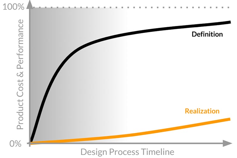
Simulation is one of the tools that play a fundamental role in those early product development stages, allowing engineers to make more informed design decisions earlier in the process. For the final product, this can mean lower production costs, more efficient energy consumption, lower failure risk, and more.
Centrifugal Pump Design Why SimScale?
Why aren’t all designers using simulation yet? Several barriers have prevented a more widespread adoption of simulation software by engineers and designers—and here’s how SimScale is aiming to challenge this status quo: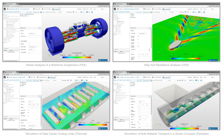
- Accessibility: Traditional software needs to be installed locally on expensive high-performing computers, most of which remain idle most of the time. With SimScale, all computations are cloud-based—all that is needed is a web browser.
-
Operating costs: Standard commercial simulation software packages are notoriously expensive. With SimScale, there is an option to start simulating right away with a free Community Plan.
-
Know-how: Most modern tools are designed for experts and experienced simulation engineers. To bridge that knowledge gap, SimScale offers a large public projects library, free training, and live support chat.
Centrifugal Pump Engineering Problem
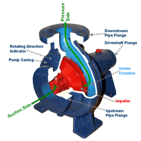
Cutaway view of a centrifugal pump (Source: By Fantagu [Public domain], from Wikimedia Commons)
A centrifugal pump essentially consists of an impeller rotating in a casing called volute. Fluid enters the eye (center) of the impeller and exits through the space between the impeller blades to the space between the impeller and casing walls. The velocity of fluid elements is in both tangential and radial directions, as the impeller rotates. The velocity and pressure both increase as the fluid flows through the impeller. Since the rotational mechanical energy is transferred to the fluid, at the discharge side of the impeller, both the pressure and kinetic energy of the water will rise. At the suction side, water is getting displaced, so a negative pressure will be induced at the eye. This low pressure helps to suck a freshwater stream into the system again, and this process continues.
The impeller is the most vital part of a centrifugal pump design. Successful impellers have been developed with many years of analysis and developmental work. The vanes (blades) of the best impellers curve backwards by design. These backwards-curved vanes have a blade angle of less than 90 degrees and are the most preferred vane type in the industry due to their self-stabilizing power consumption characteristics. This means that with an increase in flow rate, the power consumption of the pump stabilizes after a limit.

Centrifugal Pump Design Centrifugal Pump Design Optimization Study
The complexity of the flow in a turbomachine is primarily due to the 3D-developed structures involving turbulence, secondary flows, unsteadiness, etc. The centrifugal pump design process was initially based on empirical correlation, a combination of model testing, and engineering experience. Nowadays, however, the design demands a detailed understanding of the internal flow—something that is possible with the aid of CFD.
CFD simulation makes it possible to visualize the flow conditions inside a centrifugal pump and provides valuable information about the pump’s hydraulic design. Simulation results are used to calculate and predict the performance of a centrifugal pump, which replaces the lengthy and expensive physical experiments of the past. A great deal of work is saved, in addition to shortening the entire design cycle.
Centrifugal Pump Project Overview
For our case study, we will use this simulation project as a template: Centrifugal Pump Design Optimization with CFD.
This project simulates a typical centrifugal water pump using the steady-state, multiple reference frame (MRF) method and the k-omega SST turbulence model. The pressure-velocity coupling is performed through the SIMPLE algorithm. The MRF zone is assigned a rotational velocity of 157.08 rad/s (1500 rpm). The project is concerned with the influence of (1) the outlet blade angle, and (2) the number of blades on the performance of a centrifugal water pump. The performance characteristic curves, as well as the local and global flow variables, are numerically predicted using SimScale for impellers with three different outlet blade angles (i.e., 13, 23 and 33 degrees), and three different numbers of blades (i.e., 6, 8 and 10).
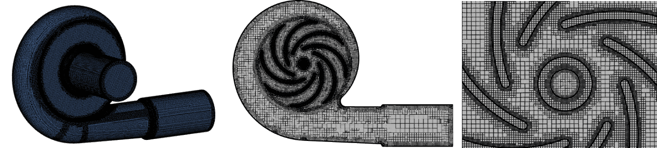
The centrifugal pump design under consideration has inlet and outlet diameters of 150mm and 151.5mm respectively, and its impeller diameter is 340mm. The domain is the geometry, which was meshed using the ‘snappy-hex-mesh’ on the SimScale platform. The resulting mesh consists of approximately 4.5 million cells, which is shown in the figure below.
Centrifugal Pump Design (1) Effect of Outlet Blade Angle Variation
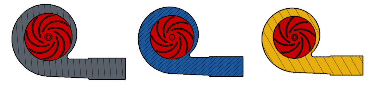
Outlet blade angle – 13, 23 and 33 degrees
Centrifugal Pump Flow Parameters
- Number of Blades = 8
- K-Omega SST Turbulence Model
- Steady-State, Incompressible Flow
- Multi-Reference-Frame (MRF) Method
- Impeller Rotational Velocity = 1500 rpm
- Inlet Volumetric Flow Rate = 540 cubic meters per hour
- Volute Casing Outlet Face — Pressure Outlet (0 Gauge Pressure)
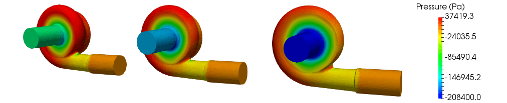
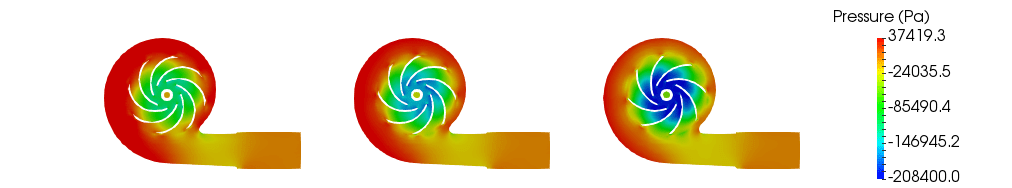
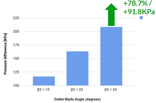
The pressure contour results show that the maximum pressure difference (208.4 KPa) between the pump inlet and outlet occurs in the pump with blade outlet angle of 33 degrees and the least at 13 degrees (116.6 KPa), and the pump outlet is set as pressure outlet with fixed value, 0 gauge pressure boundary condition.
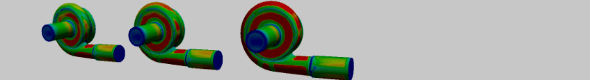
Centrifugal Pump Design (2) Effect of Variation of Number of Blades
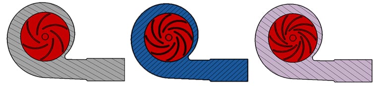
Number of blades: 6, 8 and 10 blades
Centrifugal Pump Flow Parameters
- Outlet Blade Angle = 33 Deg
- K-Omega SST Turbulence Model
- Steady-State, Incompressible Flow
- Multi-Reference-Frame (MRF) method
- Impeller Rotational Velocity = 1500 rpm
- Inlet Volumetric Flow Rate = 540 cubic meters per hour
- Volute Casing Outlet Face — Pressure Outlet (0 gauge pressure)
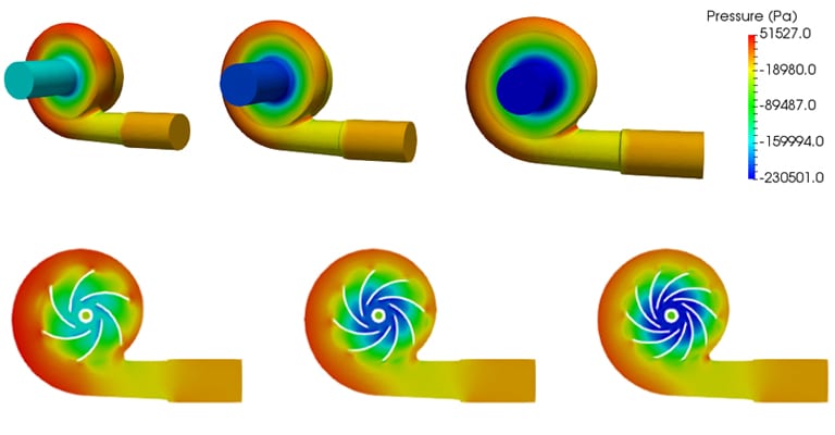
From the pressure contour results, it can be seen that the maximum pressure difference (230.5 KPa) between the pump inlet and outlet occurs in the pump with ten blades and the least at six blades (161.04 KPa).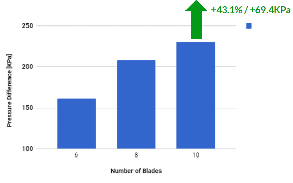
Centrifugal Pump Design Performance Comparison Between Pumps With 8 and 10 Blades (Blade Angle 30 Degrees)
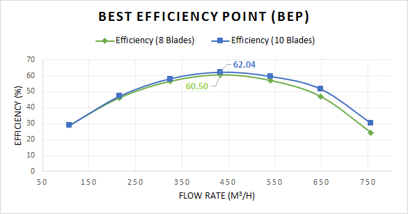
Best Efficiency Point
Best efficiency point (BEP) is the flow at which the pump operates at the highest or optimum efficiency for a given impeller diameter. BEP for this pump is obtained at the flow rate of 432 cubic meters per hour. In addition, the maximum efficiencies obtained for pumps with eight blades and ten blades are 60.5% and 62.04%, respectively.
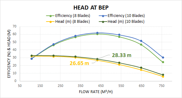
Head at Best Efficiency Point
Since the BEP occurs at a flow rate of 432 units, that flow rate also intersects the pump curve at a point equal to head of 26.65 meters, and 28.33 meters for pumps with eight blades and ten blades, respectively.
Centrifugal Pump Conclusion
As demonstrated in this case study, the centrifugal pump is a simple but essential device. Seemingly minor design changes, such as the outlet blade angle or the number of blades, can substantially impact the performance of the pump. With the multitude of available centrifugal pump design configurations, physically testing each one of them or relying on experience alone would make the design process unnecessarily long and expensive. The same design experiments can be carried out using numerical analysis and simulation, achieving equally accurate results within a few minutes or hours.
This is just one example of how CFD tools can help engineers evaluate their pumping equipment designs. The SimScale Public Projects Library has a wide selection of simulation templates covering various design aspects of industrial equipment and machinery, commercial and industrial fans, valves, and many more. In addition, you can fill in this short form to download a case study about how a ducting system design was investigated and optimized using the SimScale cloud-based platform.
References
- https://www.sciencedirect.com/science/article/pii/S1877705813001033
- https://ieeexplore.ieee.org/document/7124063/?reload=true
- https://publications.lib.chalmers.se/records/fulltext/163168.pdf
- https://publications.lib.chalmers.se/records/fulltext/179797/local_179797.pdf
- https://publications.lib.chalmers.se/publication/101019-the-ercoftac-centrifugal-pump-openfoam-case-study