Turbomachinery Simulation Software
Turbomachinery CFD Simulation. Pumps, Compressors, Turbines & Fans in the Cloud
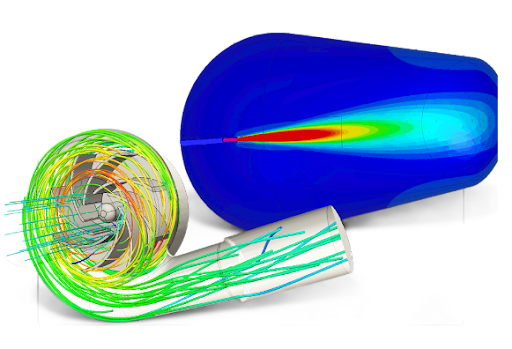
Run pumps, compressors, turbines and fans in the cloud — with Engineering AI that automates meshing and setup, and parallel performance-curve studies that return in minutes.


Turbomachinery CFD means meshing rotating zones, resolving cavitation, and sweeping full performance curves. With legacy HPC, each operating point takes hours. SimScale cuts that to minutes, running natively in the cloud.
Why SimScale for Turbomachinery Simulation

Multiphysics
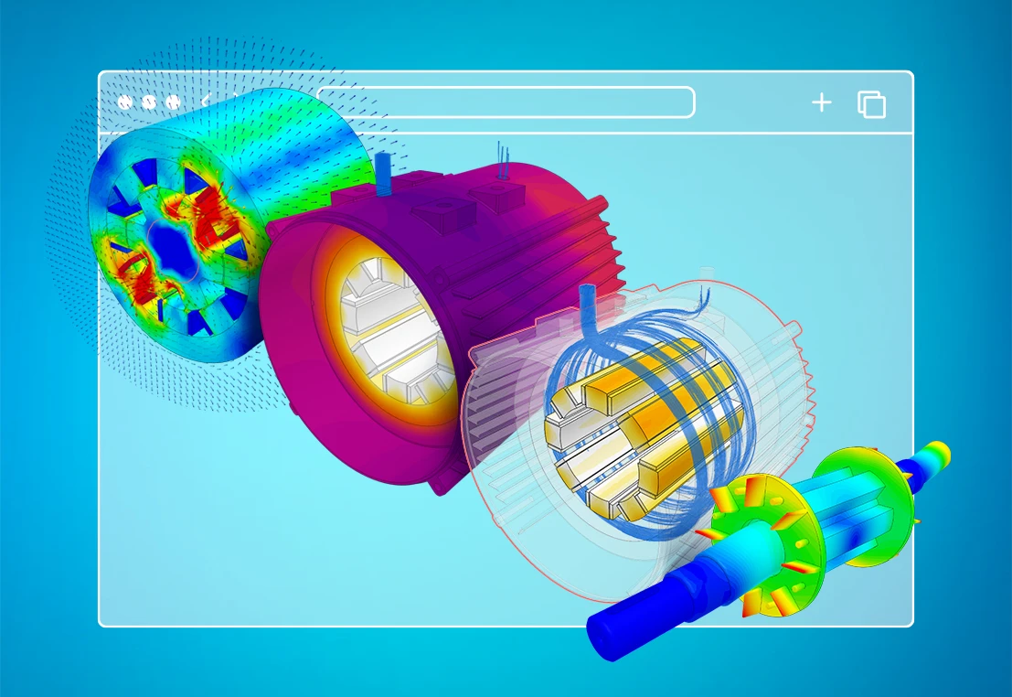
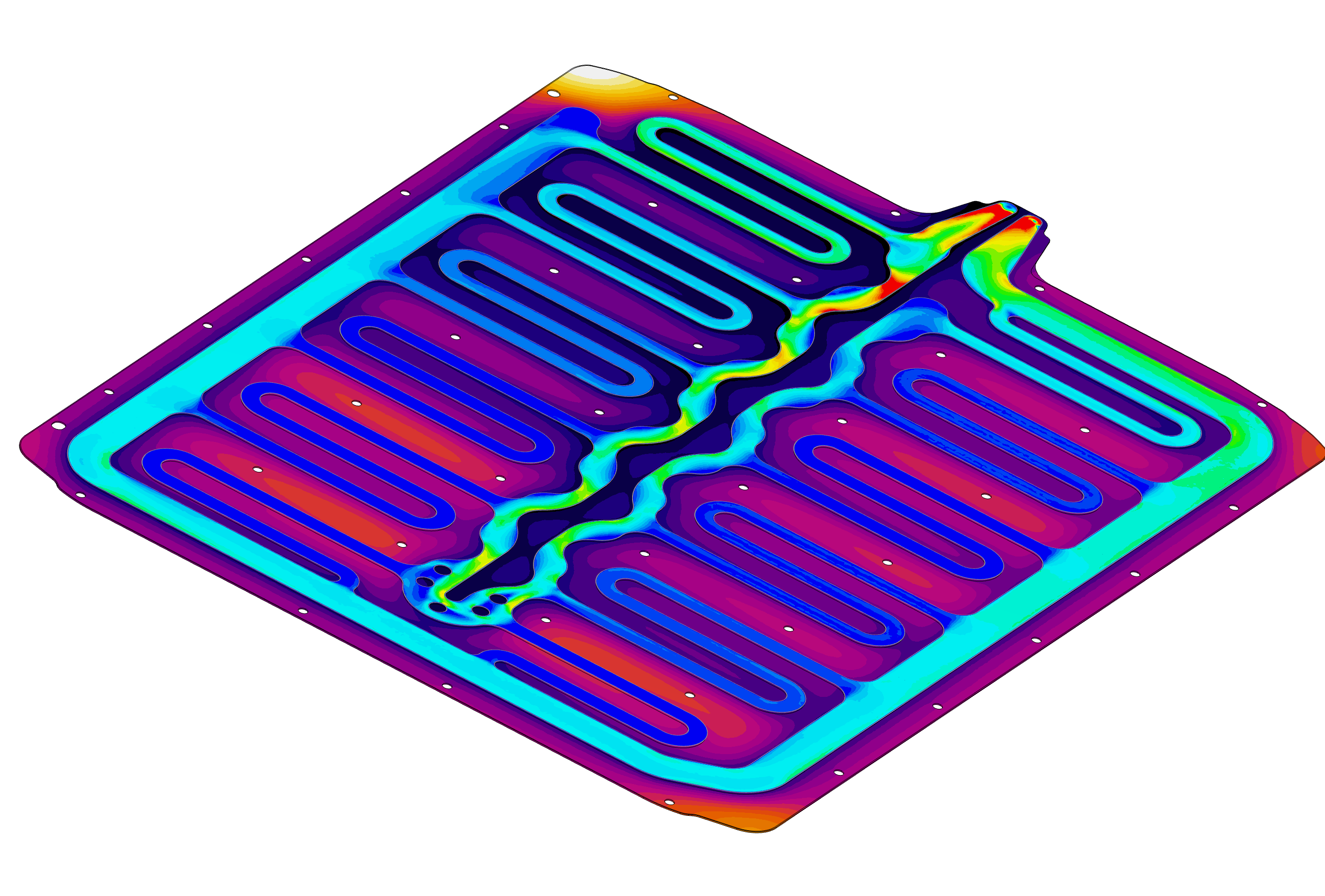
CFD, cavitation, and structural in one platform. Couple rotating-frame CFD with cavitation modeling and one-way FSI — pass dynamic flow loads onto blades to check stress and deflection, and run conjugate heat transfer, without exporting to a second tool.

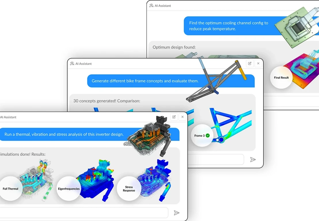
AI assisted
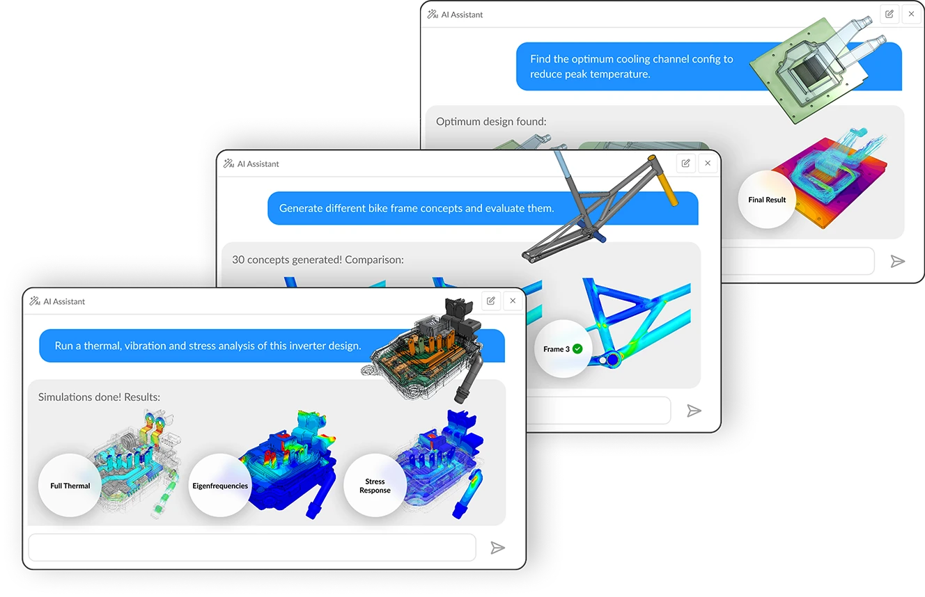
Engineering AI and Physics AI, built for rotating machinery. SimScale's Engineering AI automates meshing, boundary condition setup, and solver configuration — so design engineers, not CFD specialists, drive the workflow. Physics AI eliminates solve time on pump and impeller geometry, compressing hours of legacy computation to seconds. Both run in the browser, no HPC required.

Cloud scale
Cloud, parallel, instant. Run a full pressure-drop vs flow-rate sweep in parallel — a parametric study in nearly the same wall-clock time as a single run. No workstations, no license servers, no HPC. Share a live project link for review.

Pump & impeller design
Build the full head-flow performance curve. Simulate centrifugal and axial pumps and their impellers, build the head-flow performance curve, and run NPSHr studies. Factor cavitation directly into the CFD to find low-pressure regions before they damage hardware.

Compressor & blower simulation
No RPM limits. No regime restrictions. Model axial and centrifugal compressors, blowers, and fans across incompressible, compressible, transonic, and supersonic regimes. The Multi-purpose solver places no limit on RPM, so high-speed stages are in scope.

Turbine performance
Performance curves in minutes, not days. Run water (Francis, Kaplan, Pelton), gas, and wind turbines. Obtain the turbine performance curve in minutes, including transient and cavitation effects, and assess efficiency across operating points.

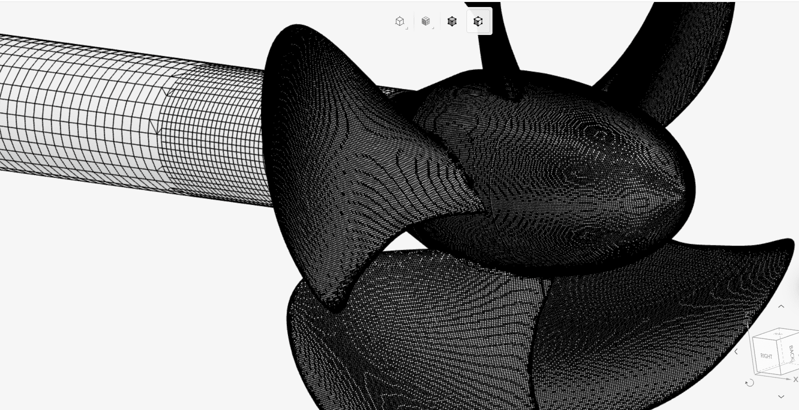
Marine propeller & thruster design
Thrust, torque, and cavitation in open water. Simulate marine propellers and thrusters to predict thrust and torque coefficients across advance ratios, map open-water efficiency, and locate tip-vortex and sheet cavitation before prototyping.

Cavitation & NPSH analysis
Find vapor formation before it damages hardware. Quantify cavitation in pumps, water turbines, and marine propellers. Results show the gas volume fraction in the liquid, so you see exactly where vapor forms — enabling NPSH studies within a day.

Stuctural analysis & FSI
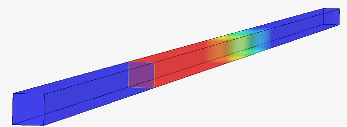
Close the loop from fluid loads to stress and vibration prediction. Pass fluid loads into a structural simulation to evaluate blade stress and deflection, and run modal analysis on towers and shafts to find eigenfrequencies before resonance becomes a field failure.
$40k
Average savings on hardware
“SimScale's customer support is positively surprising, because usually the customer pays a lot of money but needs to wait days or even weeks for support reply. SimScale service has a very clear structure, that one account manager and one support engineer are my only points of contact to listen to my request, and positively keep me updated.”
Trond Gudmundsen — Founder, Designcraft
faster
product improvements and better-informed deployments
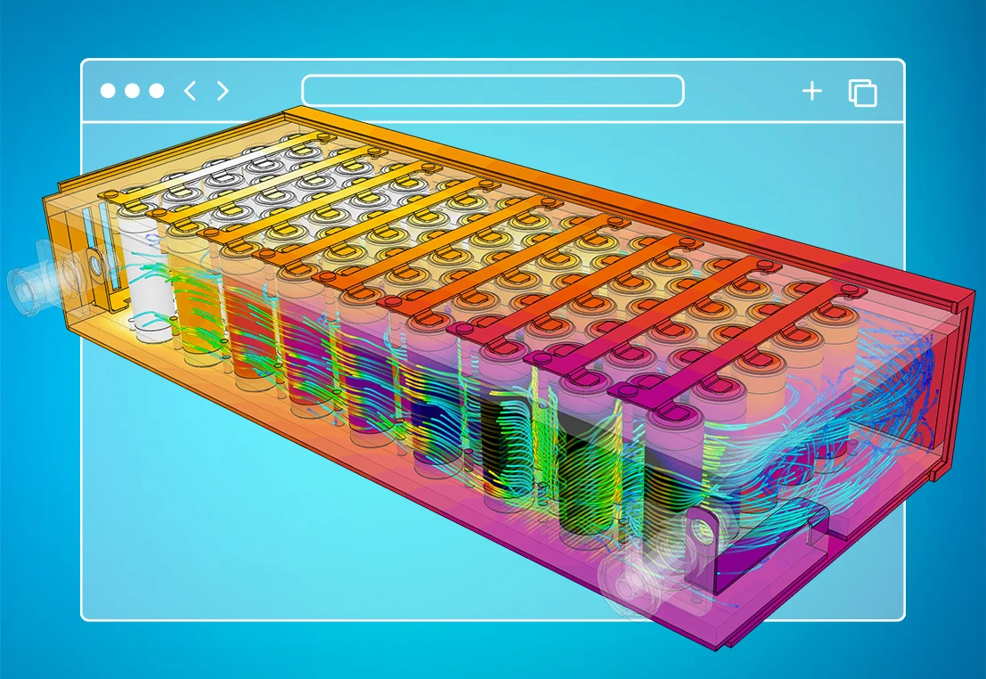
“Being able to create a digital twin of essentially any given turbine installation is becoming increasingly critical. SimScale enables us to simulate entire systems at scale—enhancing performance, reducing risk, and unlocking deployment at speed.”
Alex Stubbs — CFD Lead at Emrgy
3x
faster simulation
“Being able to run many simulations in parallel on the cloud has been very useful and saved us a lot of time. Using SimScale has reduced our wind turbine testing by weeks. By simulating on the cloud with more cores than on a personal computer, we have been getting results about 3x quicker than if we run it locally, as before.”
Julia Arnardottir - Mechanical Engineer and Simulation Expert at EM Wind
Related resources

Alex Graham
June 16, 2026
Multi-agent workflows: key takeaways from Design & Simulation Week 2026
SimScale and CoLab demonstrated live AI agent collaboration at Design & Simulation Week 2026, cutting engineering review and simulation lead times dramatically.
Alex Graham
June 12, 2026

SimScale Workflows: Why we are opening up the platform (& why you should care)
SimScale Workflows opens its platform to custom solvers and tools, enabling automated, AI-driven multi-step engineering simulation pipelines for any organization.
Alex Graham
May 29, 2026


Luis Goncaves
June 18, 2026
Luis Goncaves
January 27, 2026

Paras Ghumare
December 4, 2025


Jon Wilde
June 16, 2026


David Heiny
June 15, 2026
Jon Wilde
June 3, 2026

Peter Selmeczy
March 24, 2026
Peter Selmeczy
September 10, 2025
Peter Selmeczy
June 25, 2025

Peter Selmeczy
May 29, 2026
SimScale simulates anything that rotates within a fluid — centrifugal and axial pumps, compressors, blowers, fans, water (Francis, Kaplan, Pelton), gas and wind turbines, propellers, and impellers. It handles incompressible and compressible flow, laminar or turbulent, with cavitation and rotating-zone modeling in one framework.
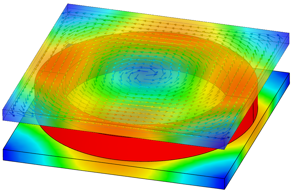
Multiple Reference Frame (MRF) is a steady-state approach used for rotors and impellers on a fixed axis — fast and economical. Sliding mesh is used for fully transient simulations and accounts for all transient effects, so it is more computationally expensive. SimScale generates the mesh interfaces between rotating and stationary components automatically for both.
Yes. Cavitation is enabled at the Create Simulation menu and modeled by computing the gas volume fraction in the liquid, so post-processing shows exactly where vapor forms in pumps, water turbines, and marine propellers. Robust convergence and fast turnaround let you complete NPSHr studies for a pump within a day.
SimScale's Multi-purpose analysis type uses a proprietary solver tailored for turbomachinery and flow control (based on the Simerics solver), plus OpenFOAM-based analysis types — delivered fully cloud-native and browser-based with parallel runs and AI-assisted setup. There is no HPC cluster, license server, or specialist install to manage, and parametric sweeps run in roughly the time of a single legacy run.
Yes. SimScale supports one-way coupled fluid-structural simulations: pass the CFD dynamic loads into a structural simulation to evaluate stress and deflection — for example, on a wind-turbine blade. You can also run modal (frequency) analysis on supporting structures such as masts and towers to find eigenfrequencies before resonance causes damage.


