Hex-dominant
The Hex-dominant meshing operation type is currently based on SnappyHexMesh, a mesh generation tool part of the OPENFOAM® open-source software. This tool generates three-dimensional unstructured or hybrid meshes consisting of hexahedra (hex) and split-hexahedra (split-hex) elements.
Generally, a reference base mesh is used to project and snap cells onto the geometry. Mesh refinements can flexibly be specified on edges, surfaces, and inside or outside volumes to obtain optimum geometry feature resolution and mesh quality. Parallel computing is fully supported with a load balancing at every iteration.
In case you’re interested in learning more details about how the hex-dominant algorithm works, take a look at the Background for Hex-dominant article in our SimWiki. The article presents a brief background of the meshing methodology used by the snappyHexMesh algorithm.
The hex-dominant meshing algorithm is currently only available for Incompressible Fluid Flow, Compressible Fluid Flow, Convective Heat Transfer, and Multiphase Fluid Flow analysis types.
Hex-dominant (Automatic)
To choose the automatic Hex-dominant meshing mode, select Hex-dominant as the meshing algorithm. Shown below are the default settings of a Hex-dominant mesh:
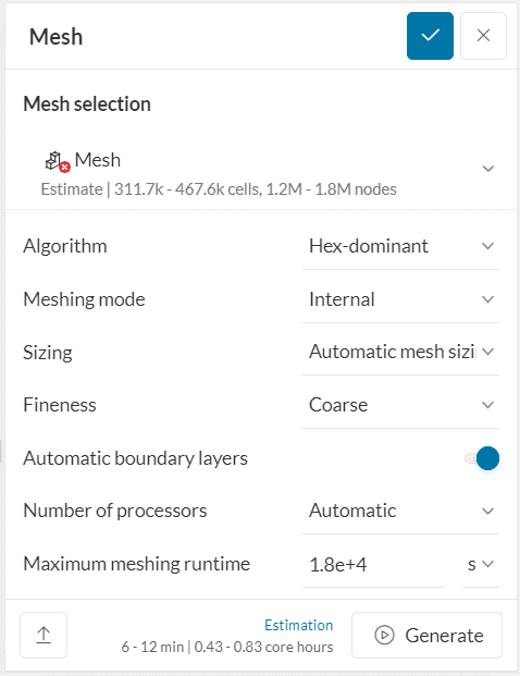
The automated Hex-dominant operation reduces the parameter set of the Hex-dominant parametric operation (below) to a minimum and sets the rest of it automatically based on the CAD domain. Use this operation to get a quick mesh to run preliminary CFD analyses. For fine-tuning the mesh for more detailed analyses the Hex-dominant parametric operation (below) provides all detailed parameters.
Meshing Mode
The meshing mode defines how the mesher should generate the mesh. There are three methods available:
- Internal meshing will place the mesh inside of the body. The Internal meshing mode is typically used for CAD geometries that already represent the final fluid domain.
- External meshing will create the mesh outside of the bodies. The overall dimension of the resulting mesh is defined by the Background Mesh Box (accessible as a Geometry primitive in the meshing tree). It is typically used for aerodynamic flows, e.g. around vehicles or buildings.
- Material point defines a point inside the domain where the mesh will be placed. The mesh will surround the material point and extend until the boundaries of the body. The material point position can be defined in the Material point geometry primitive in the meshing tree.
Another way of extracting the fluid volume from the CAD geometry is to use the Flow volume extraction feature.
Important
Generally it is recommended that the extents of the flow domain be at least 2-3D upstream, 6-8D downstream and 2-3D in the lateral directions, where D is the object reference length.
Sizing & Fineness
The sizing defines how coarse or fine the discretization of the input geometry will be. The sizing control can be set to automatic, where local properties are adjusted automatically based on geometrical estimations or a manual sizing can be applied where minimal and maximal edge length may be defined.
For the automatic sizing, only a global mesh fineness needs to be set and all additional parameters will be set automatically according to the geometry features and the chosen fineness. Its value defines the characteristic element size for each solid, ranging from 1 – very coarse to 5 – very fine. A fine mesh will result in a better resolution of small geometric features, but will also increase the computation time and memory demand of the derived simulation run. The standard setting 2 – coarse will in most cases result in a discretization that represents a good compromise between accuracy and resource consumption and should be chosen for a first trial. For mesh independence or convergence studies the sizing can be refined in later stages.
With manual sizing, the user gains full control over all details of the element sizing setup. This option provides a global minimum and maximum element edge length setting for cells of the mesh.
Hex-dominant Parametric
Besides the automatic Hex-dominant meshing algorithm, a parametric option called Hex-dominant parametric is available as well. The parametric mode exposes all parameters to the user which are also available in the original “SnappyHexMesh” tool from OpenFOAM. This meshing algorithm allows you to create high-quality hex-dominant meshes for arbitrary geometries with optionally refined boundary layers.
A detailed documentation of the available settings can be found in two parts:
- Main settings for Hex-dominant parametric, details the primary settings that must be set by the user. These settings contribute to the most important part of the meshing process and will dominantly affect the resulting mesh. In general, an average user is expected to input only those settings for a mesh.
- Advanced settings for Hex-dominant parametric, provides brief details of the advanced settings. For an average user, it is normally not recommended to change these settings as the default values are selected to be optimal. However, based on the needs and requirements of the mesh these can be adjusted as required.
Note
Please note that all operations based on snappyHexMesh create polyhedral meshes which means that they can include cells of arbitrary shape. Therefore these meshes can not be used for Finite Element analysis but only for Finite Volume based solvers like OPENFOAM®.
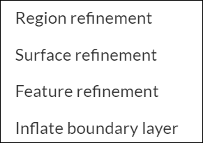
Mesh refinements
Mesh refinements can be used to refine (or coarsen) the mesh locally and only where it is needed. This allows the generation of very efficient meshes with respect to considerations about result accuracy versus computational resource demand.
A mesh refinement can be added via the Refinements node in the meshing tree. Current mesh refinement types available are Feature refinement, Region refinement, Surface refinement, and Boundary layer inflation.
Local settings will always override the global setup for the assigned entities. If multiple refinements of the same type are defined on the same entities this might lead to conflicts and thus should be avoided.
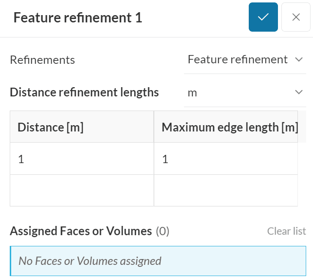
Feature refinement
A feature refinement can be used to refine the geometry’s feature edges. All edges whose adjacent surface normals have an angle less than 150° are marked for extraction and refinement.
Refinement settings include Distance and the Length. The edge and surface mesh will then be refined up until the specified distance in all directions from the extracted edges. The length parameter determines the intended cell edge length.
A default feature refinement is always included when using the Hex-dominant automatic meshing type. This refinement type can be used to modify the default behavior.
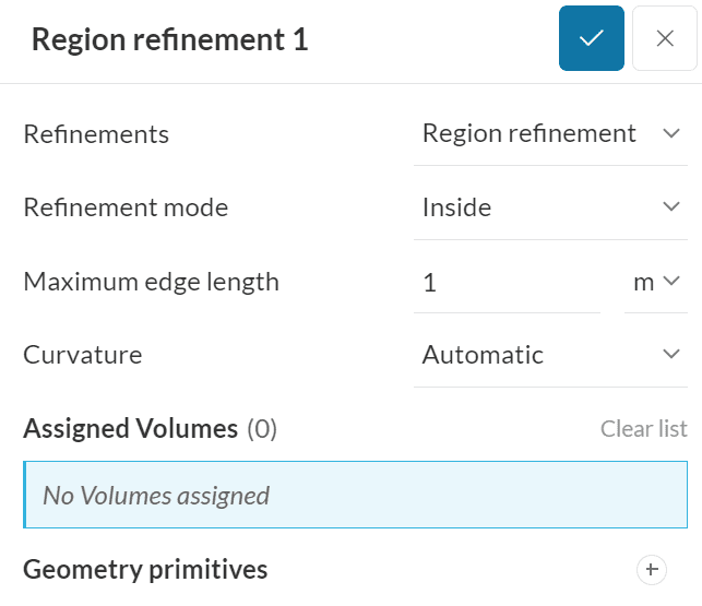
Region refinement
The region refinement is used to refine the volume mesh for one or more user specified volume regions. It’s possible to assign CAD entities as well as user-defined geometry primitives. One of the following refinement modes can be used:
- Inside: Refines all volume mesh cells inside the selected volumes up to the specified cell edge length.
- Outside: Refines the outside volume mesh cells up to the specified cell edge length.
- Distance: Refines according to distance to the surface of the assigned volumes. The Distance mode can accommodate different refinement levels at multiple distances. It is important to note that the distances need to be specified in descending order.
Surface refinement
A surface refinement can be applied to refine cells on specific surfaces of the geometry. Both geometry faces and/or volumes can be selected for refinement. If a volume has been assigned, the refinement is applied to all surfaces of that volume. Surface refinements can also be used to group cells together – such a group of cells is called a cell zone.
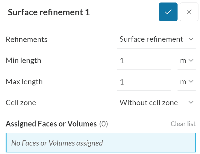
It’s required to specify two refinement levels, the minimum cell edge length and the maximum cell edge length. In the first step, a refinement up to the maximum length is applied across all of the assigned surfaces. Further refinement up to the minimum cell edge length is only applied to cells in areas where the normals form an angle greater than 30°. Therefore, in the following cases, only the first refinement step is applied:
- A flat surface
- A surface that has an angle between normals less than 30°
It is recommended that the maximum level be set to give a cell size in the order of the minimum surface dimension.
By default, the option to create a cell zone is inactive. For a cell zone to be created, a closed volume needs to be assigned to the surface refinement and the cell zone option needs to be enabled. If successful, all cells enclosed by the assigned volume will be grouped together.
Cell zones are required to assign specific properties to a sub-set of cells, like defining it as an MRF (Multiple Reference Frame) or AMI (Arbitrary Mesh Interface) rotating region, a momentum source, a heat source, porous media, or a passive scalar source. If the geometry that is being meshed is of STL format, the user can also assign a list of faces that form a closed volume to create a cell zone.
Note
The surface refinement will be overwritten by a feature refinement at the geometry edges up to the specified feature refinement distance.
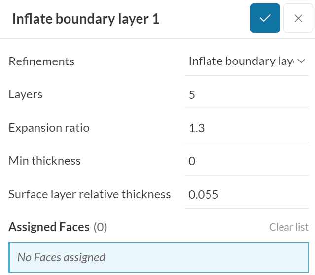
Inflate boundary layer
The inflate layer refinement adds a volume mesh with cells aligned to the surface of all assigned surfaces. Only faces of the geometry domain can be assigned for refinement. The following four parameters are required inputs:
- Layers: Specifies the total number of layers to be added.
- Expansion ratio: Specifies the growth of successive layers. The larger the value the greater the difference in height between the layers.
- Min. thickness: This specifies the overall minimum thickness of all the layers combined. In case the overall thickness of all layers falls under this minimum thickness, layer addition will be stopped for the affected areas and no layers will be added there.
- First Layer Thickness: Specifies the height (thickness) of the first layer that is closest to the surface. The first layer thickness is specified relative to the neighboring volume cell size after refinements.
The layer mesh will be inserted between the surface and first volume cell layer by pushing the existing mesh out. To keep mesh distortion effects small, the total layer mesh thickness should not exceed the thickness of the first volume cell layer thickness.
Tutorials
A list of meshing tutorials can be found in the tutorial section.
Disclaimer
This offering is not approved or endorsed by OpenCFD Limited, producer and distributor of the OpenFOAM software and owner of the OPENFOAM® and OpenCFD® trade marks. OPENFOAM® is a registered trade mark of OpenCFD Limited, producer and distributor of the OpenFOAM software.
Last updated: December 30th, 2025
Did this article solve your issue?
How can we do better?
We appreciate and value your feedback.
What's Next
Main Settings for Hex-dominant Parametricpart of: Meshing in SimScale


