Simulation Setup
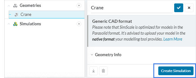
The SimScale Workbench is designed as a single interface for the application of multiple simulation types. After you have prepared and uploaded your CAD model into the Workbench, you are ready to set up your simulation. The first step you will need to do is choose an analysis type, to choose an analysis type, click on the ‘Create Simulation’ button in the geometry dialog box or click on the ‘+’ sign besides Simulations in the navigation tree as circled below:
Following the above steps a window that contains all the available analysis are shown:
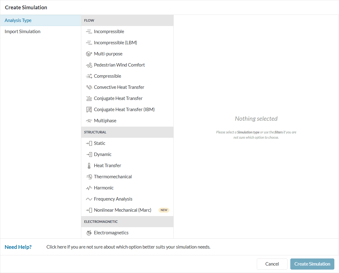
Hit ‘Create Simulation’ one more time and you are good to go. A simulation tree will appear showing the steps necessary for that particular simulation setup.
Note
This page provides a general information on how to setup a simulation. Some elements in the simulation tree will only be available for certain analysis types, for example, contacts will only be available for structural analysis. Know more about individual analysis types here.
Simulation Tree
The simulation tree shows the steps necessary for the user to define before the simulation can run.
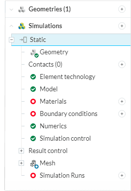
Some steps will have different status icons, this describes whether the corresponding step needs to be configured by the user or not. The colors and their description can be seen below:
- Incomplete state
 : This symbol means that the user will have to define the corresponding setting to be able to run a simulation because it is a critical setting. For example Material and Boundary conditions.
 - Complete state
 : The user does not need to configure this step further unless it is necessary to do so. For example Geometry, Numerics, and Simulation control.
 - Optional state
 : The user will have to check the corresponding setting to inspect whether it can be applied for the specific simulation indicating that it is optional. For example, Mesh.
 - Error state
 : This symbol means that there has been an error in the corresponding settings. For example, no values have been set for a boundary condition or using negative flow rate values.
Global Settings
In the global settings, the user can change the behavior of the model used for the simulation. For example, in a static analysis, a choice between linear and non-linear analysis or the type of turbulence model applicable to fluid flow can be made.
One can find the settings that are a part of the global settings here.
Geometry
The geometry displays all the uploaded geometry in the project. The user can switch between geometries for the same simulation analysis. One will be able to use different design iterations for the same simulation settings, however, if the faces of the geometry are different the user will need to re-assign the other settings once more.
The user can find more information regarding the requirements for the geometry for a simulation here.
Geometry Primitives
Geometry primitives are primitive shapes in the form of a cartesian box, cylinder, sphere, and point that can be used to apply settings to only a specific part of the simulation model. Learn more.
Contacts
Defining contacts is necessary in cases when the simulation domain doesn’t consist of one part – built from a single material, but an assembly of parts, often built from different materials, and even combining fluids and solids in the case of multi-physics simulations. Learn more.
Connectors
Connectors help to reduce the complexity of a multipart structural analysis. This is achieved by defining the connection between multiple parts, without the need for a physical component.
Element Technology
Element technology refers to the numerical formulation for the solid finite element used in the simulation. This includes the mesh order, reduced integration, and mass lumping. Read more about element technology in this documentation page.
Model
Under the Model tab, additional parameters like gravity, passive species, geometric behavior, etc. that define the physics of the simulation are defined.
Materials
This is where the user defines the simulated material, such as the fluid in a CFD simulation or the material of a solid in a structural analysis. The user can use a predefined material that is available in SimScale or use a custom material by changing the physical properties of the material.
Note
Read more about how to define custom materials here.
One can find more information regarding the materials and their behavior here.
Initial Conditions
The user can set an initial condition for the simulation globally or via subdomain(s). Initial conditions can help in reaching a converged solution faster which saves you computing resources. One can assign initial conditions either as uniform or in subdomains.
Interested readers are referred here for more information.
Boundary Conditions
Boundary conditions define how a system (structure or fluid) interacts with its environment. The inlet and outlet are examples of a boundary condition for a flow simulation while the load and pressure are for an FEA simulation. The lists of boundary conditions available will differ depending on the type of simulation selected beforehand.
More information about boundary conditions for each analysis type can be read here.
Advanced Concepts
You can define complex models, such as rotating zones, porous media, and momentum sources to model accurate physical conditions for a problem leading to more accurate results when dealing with models such as fans, turbines, tress representing a porous media, etc.
The user can find information regarding the available advanced concepts that can be applied in a simulation here.
Numerics
The user can configure the equation solver for the simulation, change the convergence settings, and other numerical settings necessary to reach a converged solution. However, it is worth keeping in mind that this is for advanced users only. For most of the cases, default settings are enough.
This is the brains behind running the simulation. Here, you have control over the schemes, solvers, relaxation factors, tolerances, etc that can lead to a successful and efficient solving of a simulation problem. Through these settings, you can control the convergence and stability. It is worth keeping in mind that this is for advanced users only. For most of the cases, default settings are enough.
More details about numerics are accessible here for CFD and on this blog for FEA.
Simulation Control
This is where the user can configure the amount of time the simulation is allowed to run, the number of results that will be saved, and the number of processors that will be used in the simulation.
The user can find more information about how to control the simulation here.
Result Control
If necessary, the user can define additional results to be exported. For example, forces and moments, surface data, and field calculations are some of the additional results that can be exported. The user can also place probe points in the model.
One can read more about how to control the outputs of the result here.
Mesh
This is where the discretization of the model is defined. The user can choose the meshing algorithm and the level of fineness that the mesh needs to achieve. The quality of the mesh heavily influences whether the simulation can be run or if the results are accurate enough. The user can also create multiple meshes for one geometry. Experience the Hex-dominant or the new standard mesher today.
The user can find an explanation about meshing and more information regarding the mesh settings here.
Simulation Run
After the user has defined the necessary settings, the simulation is ready to run. One can name each simulation run to their liking to easily differentiate between simulation runs if multiple runs are in the plan.
Note
If you have questions or suggestions, please reach out either via the forum or contact us directly.
Last updated: June 18th, 2026
Did this article solve your issue?
How can we do better?
We appreciate and value your feedback.


