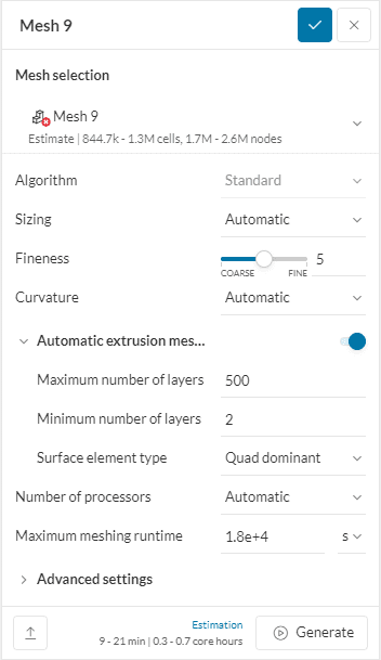
Standard Mesher
The Standard mesher operation type uses a finite-volume mesher. This tool generates a three-dimensional unstructured mesh using tetrahedral or hexahedral elements.
Shown below are the default settings that the mesh will contain:
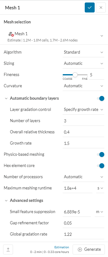
Default Settings
Sizing and Fineness
The Sizing defines how coarse or fine the discretization of the input geometry will be. The sizing control can be set to automatic, where local properties are adjusted automatically based on geometrical estimations. Manual sizing can also be applied where a minimum and a maximum edge length can be defined.
Automatic Sizing
For the automatic sizing, only a global mesh fineness needs to be defined and all additional parameters will be set automatically according to the geometry features and the chosen fineness. Its value defines the characteristic element size for each solid, ranging from 1 – very coarse to 10 – very fine.
A fine mesh will result in a better resolution of small geometric features, but will also increase the computation time and memory demand of the simulation. The standard setting of 5 (moderate) will usually provide a good compromise between accuracy and resource consumption and is recommended for a first trial.
For mesh independence or convergence studies the sizing can be refined.
Manual Sizing
Manual sizing gives you the freedom to define the maximum edge length and the minimum edge length of the cells. The intermediate cell size is adjusted accordingly.
Curvature
This feature allows the user to specify the mesh refinement on curved features. By default, this is Automatic. Alternatively, it is possible to specify the curvature in terms of the number of mesh nodes in a circle using the Relative option. Curvature refinement is not supported with geometry primitives but can be used with surface and volume custom refinements.
Mesh Order for Structural Simulations
For Structural simulations (solid mechanics) the mechanical and thermal order of the mesh, i.e., first or second order, can be defined under the Element technology item in the simulation tree.
Automatic Boundary Layers
This feature, when enabled, builds layered mesh cells next to only those surfaces of the CAD model which are assigned a wall boundary condition. The settings and their functions are the same as described for inflate boundary layer feature below.
Physics-Based Meshing
This feature, when enabled, builds the mesh taking into account the information entered as a part of the simulation setup. This important information ranges from the material properties, boundary conditions, additional source terms (e.g., momentum and power sources), etc. Essentially, the physics involved in the fluid simulation is given priority while sizing the mesh elements.
The following adaptations are primarily observed when Physics-based meshing is toggled on:
- Mesh refinement at the inlet and outlet of the domain
- Additional operations on the boundary layers at the walls
Important
If you attempt to generate a mesh with physics-based meshing enabled while the simulation setup is invalid, the following error message will appear:
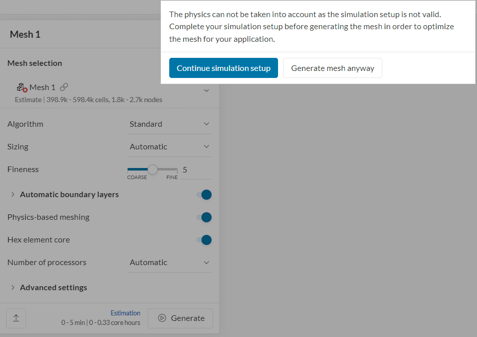
The message above means that the current simulation setup is invalid. This could happen for many reasons, for example:
If this warning message comes up, the recommendation is to click on ‘Continue simulation setup’ and fix the problematic settings in the simulation setup. The easiest way to find out what the invalid settings are is by attempting to start a simulation:
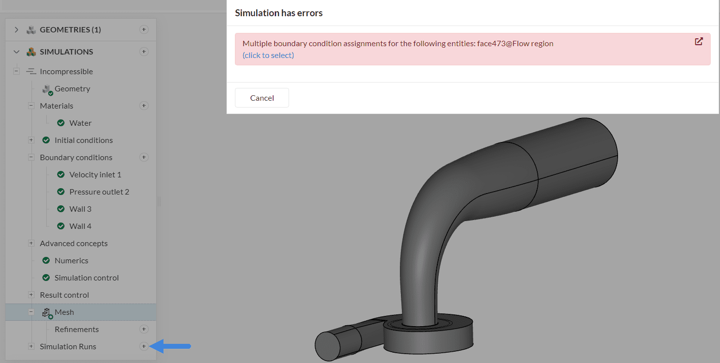
By going through the list of invalid settings, it is possible to fix the simulation setup and proceed with the mesh generation normally.
Hex Element Core
The feature is only available in CFD meshes and defaults to ‘on’. When activated the interior of the mesh gets covered with hexahedral elements. The transition from hexahedral to triangulated surface mesh is done using pyramidal and tetrahedral elements.
It is recommended to leave the default settings alone.
Number of Processors
This defines the machine size that the mesh will be created on. Most meshes will be successful on a 16-core machine and this is a great starting point.
Learn with the video!
Here’s a short video on the Basics of Meshing in SimScale. It explains different parameters from the mesh settings panel.
Advanced Settings
When set to zero, advanced settings do not affect the meshing process. Two options can prove helpful when working with highly detailed geometry.
Small Feature Suppression
This can be used to ignore small surfaces during the meshing process. It essentially merges surfaces to avoid unnecessary levels of refinement around small features.
You get to define a minimum edge length below which small features like tiny edges or sliver faces should not be resolved during meshing. Setting it to ‘0’ would mean a request to resolve every detail leading to a large mesh size.
Gap Refinement Factor
This feature enables users to better capture small gaps in the model. For example, the air between the fins of a heat sink or even the solid heat-sink fins themselves.
The gap refinement factor is better defined as the ratio between the gap thickness and the mesh edge length in the gap:
- For values > 1, the value (integer) is also the number of elements across the gap.
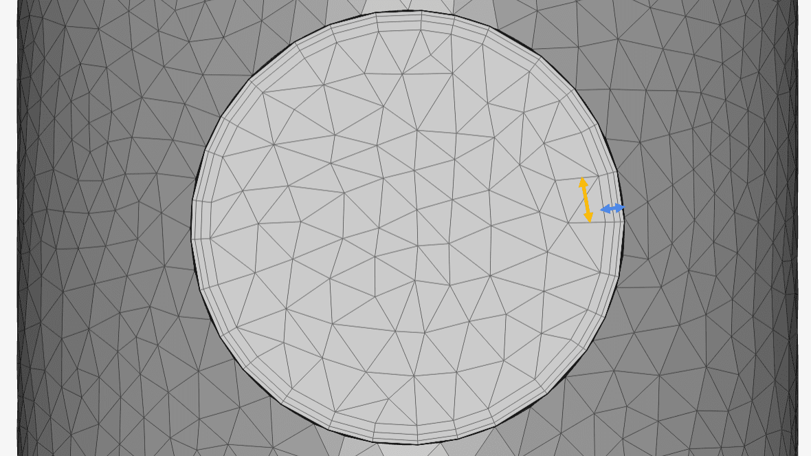
- For values < 1, the gap refinement factor is the inverse of the aspect ratio of the elements in the gap (see picture below).
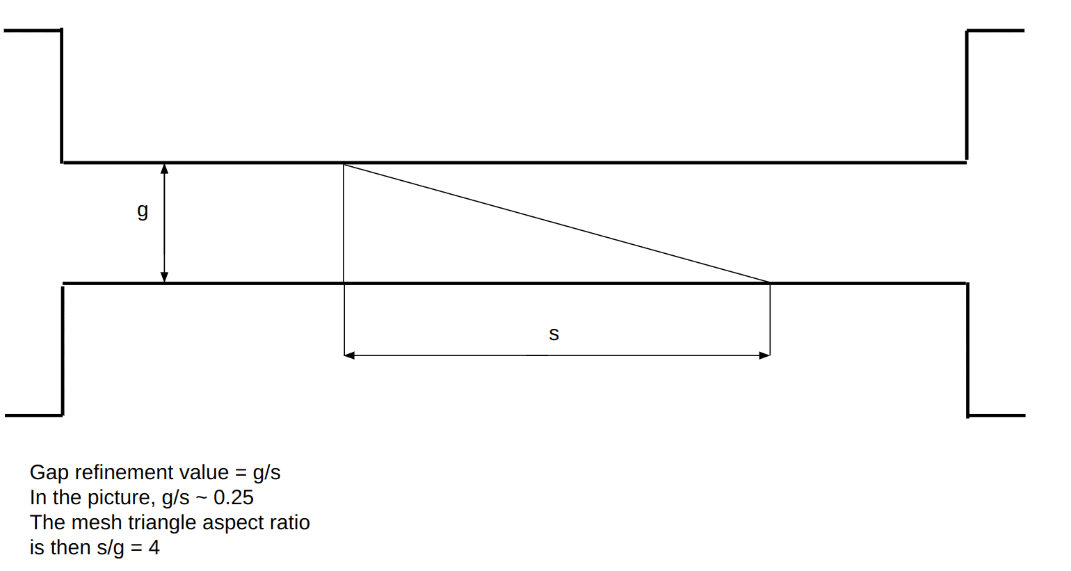
The default value of 0.05 is there to guarantee that the elements across a thin gap are not too flat causing quality to decrease substantially.
The feature does not guarantee a specific number of cells across the gap thickness since it is dependent on the algorithm’s constraints to accommodate the right amount of cells by an approximate gap thickness to desired cell size ratio. For example, if a value of 1.5 is entered, it is expected that 1-2 cells will be accommodated across the minimum gap thickness, and this will naturally change when the gap thickness gradually increases.
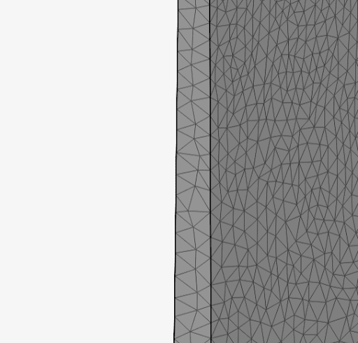
Consider the following image of a meshed “gap” which has a slight taper for illustration purposes. Note how setting a gap refinement factor for 2 accommodates the cells in the small gap thickness.
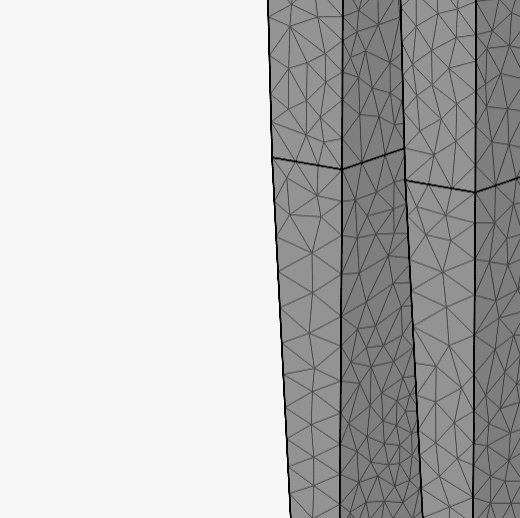
For the same meshed solid, notice how the number of cells across the gap change as the thickness increases further for the same gap refinement factor of 2. So as explained earlier, the factor does not guarantee a specific number of cells across the gap and is dependent on constraints on the mesher that need to be taken into account for a consistent mesh.
Global Gradation Rate
The Global gradation rate is the ratio between the size of two adjacent cells in the computational domain. This setting controls how quickly the cells transition from small to large.
The global gradation rate can receive any value between 1 and 3. By default, it has a value of 1.22, which is a good compromise between cell size transition and mesh size. Defining a gradation rate of 1 causes the resulting mesh to be uniform, with the smallest cell size everywhere. For larger gradation rates, the transition from small to large cells accelerates.
Setting a value of 1 is not recommended, since the resulting meshes may be very large. Similarly, setting large values for the gradation rate is also not desired, as the cell size transition will be abrupt.
Mesh Refinements
Mesh refinements can be used to refine the mesh locally and only where it is needed. This enables the generation of very efficient meshes concerning result accuracy versus computational resource demand.
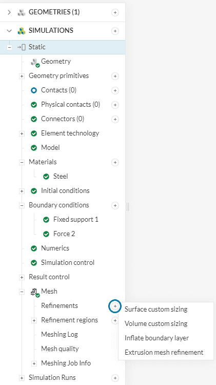
A mesh refinement can be added via the Refinements node in the meshing tree. Current mesh refinement types allowed are:
- Surface Custom Sizing
- Volume Custom Sizing
- Inflate Boundary Layer
- Extrusion Mesh Refinement
Important
Local settings will always override the global setup for the assigned entities. If multiple refinements of the same type are defined on the same entities, the algorithm opts for the finer setting irrespective of the order in which the refinement levels were assigned. Multi-refinement, however, should be avoided for clarity purposes.
Surface Custom Sizing
Surface custom sizing is used to define local element size to faces.
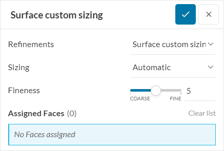
Automatic Sizing
The surface custom sizing refinement allows an Automatic sizing based on a Fineness of interest. This option allows to generate a mesh with a finer or coarser size than the global value.
Custom Sizing
Alternatively, a Custom sizing allows the definition of Default and Minimum size, where the Default option sets the desired size for mesh elements. While the algorithm strives to achieve the specified cell size, it may not always be applied uniformly. In cases where mesh quality constraints or intricate geometrical features are present, the algorithm will automatically use a finer mesh. The Minimum edge length, if set above zero, defines the target minimum edge length in the mesh. The same concept applied to the Default option is applied here concerning the constraint on respecting the specified size. The Curvature parameters can also be changed in order to refine the selected faces.
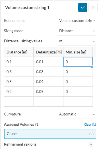
Volume Custom Sizing
The volume custom sizing refinement can be assigned to parts or geometry primitives.

Note
If the goal to apply refinement to a specific geometry primitive that intersects a volume, there’s no need to assign the volume explicitly. Simply leave the Assigned Volumes field empty.
Automatic Sizing
When using an Automatic sizing, the mesh element sizing is controlled by automatic Fineness levels, which take the geometrical properties into account.
Custom Sizing
It is possible to use a Custom sizing, allowing the definition of a Default and Minimum element size within the selected regions. Similar to Surface custom sizing, the Default option sets the desired size for mesh elements, and the minimum edge length, if set above zero, defines the target minimum edge length in the mesh. The Curvature parameters can also be changed in order to refine the selected parts.
Sizing Modes
For the Standard mesher, there are two types of sizing modes available: Inside and Distance.
Inside: Refines all volume mesh cells inside the selected volumes up to the specified cell maximum edge length.
Distance: Refines mesh cells according to the distance to the surface of the assigned volume(s). The Distance mode can accommodate different refinement levels at multiple distances. The smallest value for Default size must be assigned to the smallest Distance. In other words, the value for edge length must increase as the distance from the surface of the volume increases. (The order in which entries are made in the table does not matter)
Note
Volume custom sizing refines everything within the selected assignment. Therefore, when assigning volume and geometry primitive at the same time, pay attention to what is common between them.
If the assigned geometry primitive is completely enclosed within the assigned volume, then the volume assignment will override the geometry primitive. This means if you only want to refine a certain region of a volume (or part), then only use geometry primitive and do not assign the entire volume.
Inflate Boundary Layer
This adds a volume mesh with prismatic cells aligned to the surface of the assigned faces. Only faces of the geometry domain can be assigned for refinement. This feature is generally used to refine the boundary layer to capture it better. The following four parameters are required as inputs:
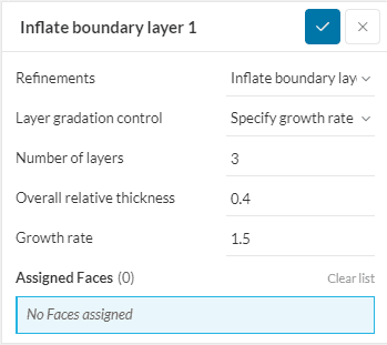
- Number of Layers: Specifies the total number of layers to be added.
- Overall Relative Thickness: Specifies the overall thickness of all layers combined, relative to the surface mesh element adjacent to the boundary layers. It is not recommended to set this value below 0.25.
- Layer Gradation Control:
- Specify growth rate: Specify the growth rate that controls the relative sizing between elements of adjacent layers. 1.5 means a 50% difference between layers.
- Specify first layer thickness: Specify the first layer size that fixes the absolute height of the first element next to the wall.
- Specify first layer and total absolute thickness: Define the absolute value of the first layer and the total layer thickness. The growth rate is computed automatically using a geometric progression.
Automatic Extrusion Meshing
This meshing type automatically enables structured mesh, only for CFD and FEA simulations. When enabled, the toggle shows an initially collapsed drop-down menu with relevant options for sweep meshing.
The available options are:
- Maximum number of layers: It caps the number of layers along the sweep to the specified maximum value (default is 500).
- Minimum number of layers: It caps the number of layers along the sweep to the specified minimum value (default is 2).
- Surface element type: Either Quad (default) or triangles, it specifies the element type on all start/end faces of the sweepable bodies.
Extrusion Mesh Refinement
This refinement option combines the ability to create a sweep refinement and add thick layers in a single feature.
The following settings are required in the setup:
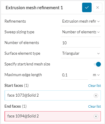
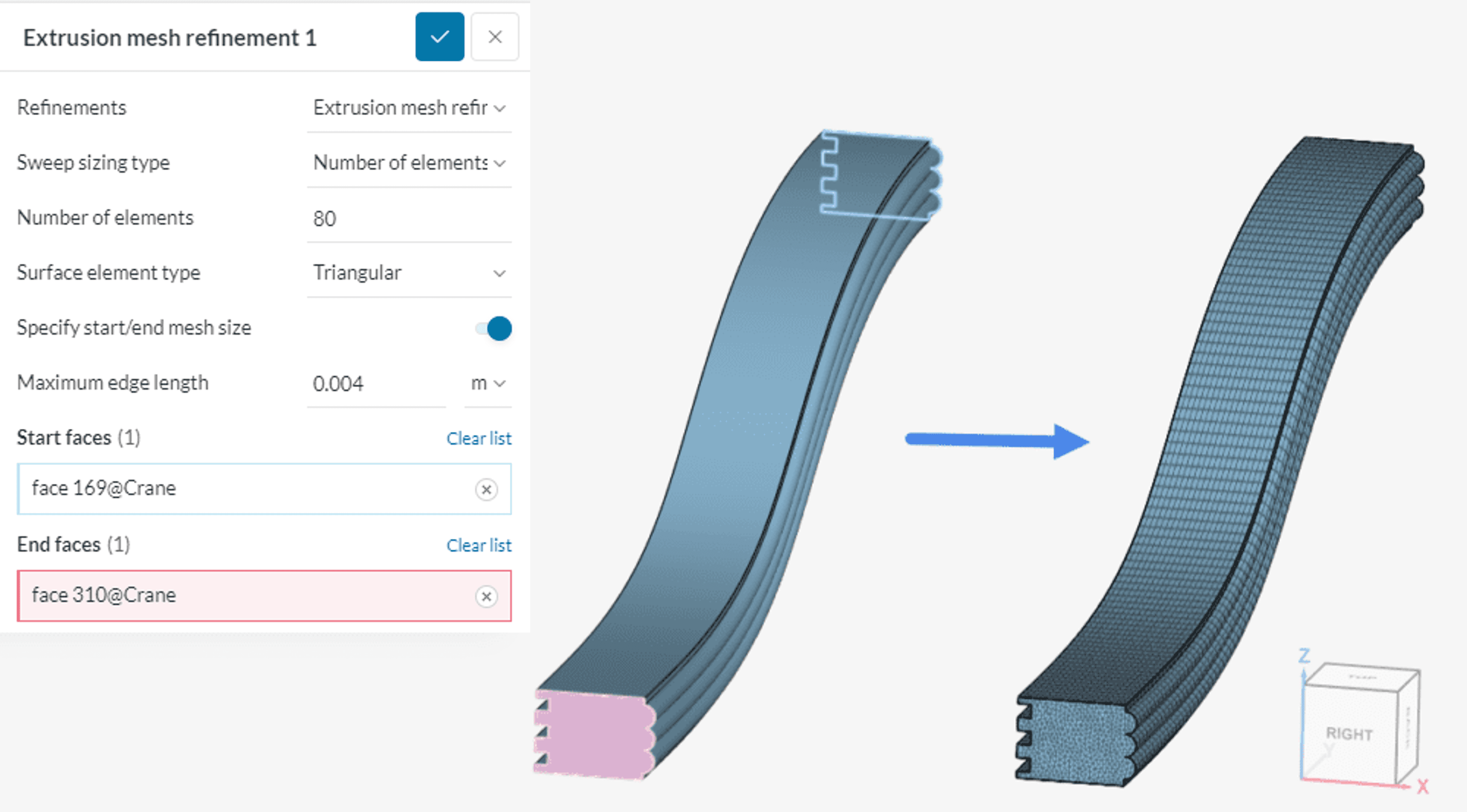
- Sweep sizing type: The user can define the Number of elements or the Element thickness along sweep. These parameters control the number of prism layers between the Start and End faces. For example, in the figure below, a total of 80 prism layers were created in the y-direction.
- Surface element type: With this setting, the user defines the type of cells to be generated on the start and end faces. In Triangular mode, the mesh cells will be prisms with a triangular base. In Quad dominant mode, the mesh will consist mainly of hexahedrons and possibly some triangular-based cells.
- Specify start/end mesh size: If toggled on, this option allows the user to control the maximum edge length of the cells on the start and end faces.
- Start and End faces: The user needs to define one Start and one End face that belongs to the same volume. Note that several volumes can have their start and end faces assigned to the same refinement, as long as each volume has a single start and end face.
If you select start and end faces that represent a path on the same solid, the refinement will generate a mesh with layers along the solid with sweeping behavior. Please note that this refinement only works for bodies that can be entirely swept.
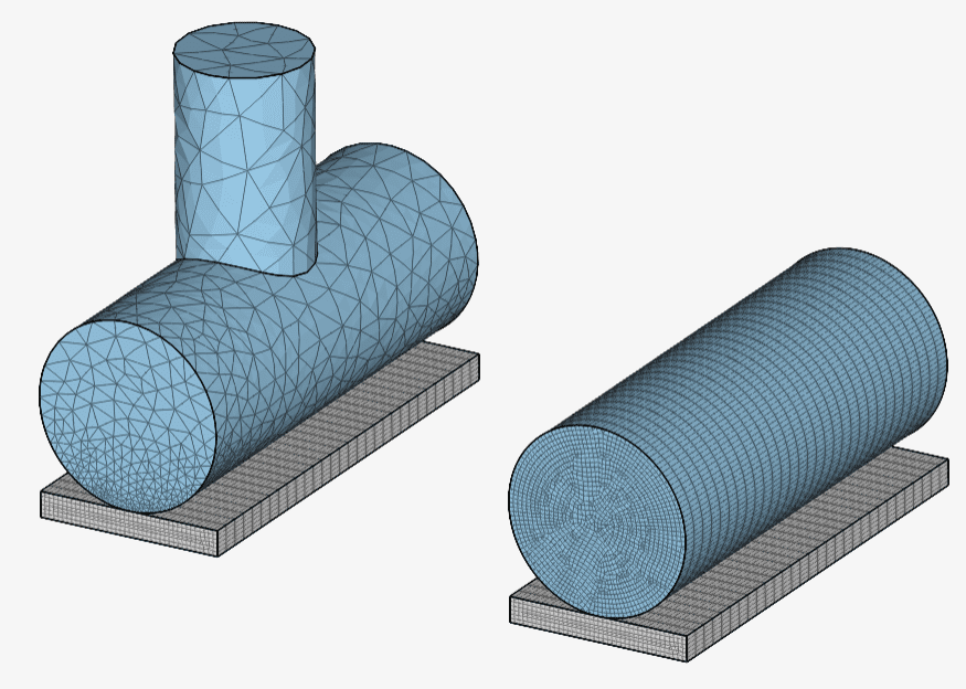
The refinement can also be applied to cylindrical regions or sweepable bodies, allowing the method to generate a more structured mesh using quad elements.
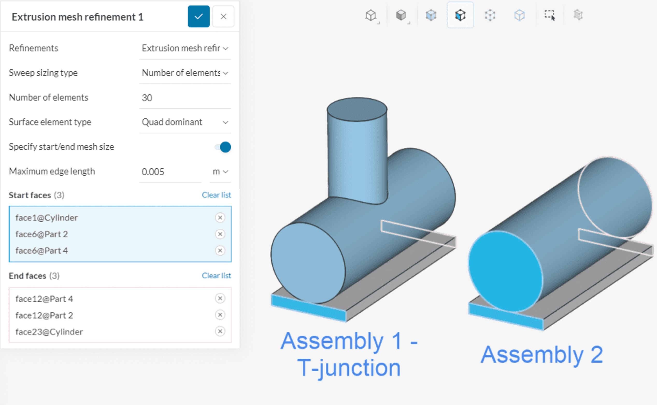
The result of the mesh settings shown above is the following:
The Extrusion Mesh Refinement can also be used to create a structured mesh with multiple layers on a portion of the geometry, ideally a thin wall. It is necessary to define a linear path between the faces in a thin direction. Also, this approach can fully or partially fill the geometry region.
Cell Zones
A cell zone is a collection of cells grouped. It is a part (volume) of the CAD model that needs to be present before the model is imported to the Workbench. Cell zones are required to assign specific properties to a subset of cells, like defining it as a rotating region (MRF-Multiple Reference Frame or AMI-Arbitrary Mesh Interface), a momentum source, a power source, porous media, or a passive scalar source. This feature only appears when the Physics-based meshing feature is toggled off.
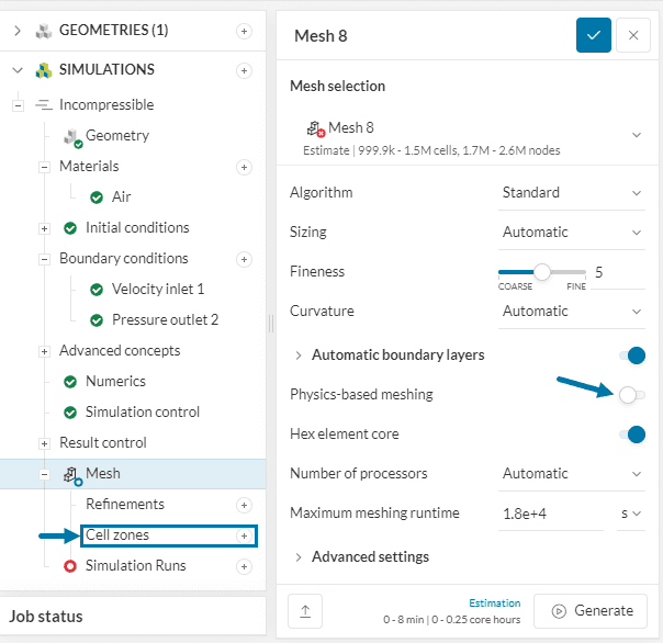
When Physics-based meshing is toggled on users don’t have to worry about creating a separate cell zone as it will automatically be taken care of. This saves a lot of time that would otherwise be spent creating cell zones one by one in case there are plenty of them.
Tutorials
A list of meshing tutorials can be found in the tutorial section.
Last updated: February 26th, 2026
Did this article solve your issue?
How can we do better?
We appreciate and value your feedback.
What's Next
Standard Mesherpart of: Meshing in SimScale


