Geometry Primitives
Geometry primitives are primitive shapes that can be used for multiple purposes during the simulation setup. If you want to capture a part of the CAD geometry to apply certain simulation settings like additional mesh refinement, presence of a power or a momentum source, monitoring result controls then creating primitive shapes and assigning them comes handy. In this document, we will go through the types of primitives supported by SimScale, as well as their applications.
Creating Geometry Primitives
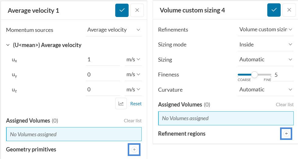
Geometry primitives can be created from within the corresponding simulation settings that may require them. For e.g., while creating advanced concepts (like passive scalar sources or Momentum Sources) the settings panel gives the user an opportunity to create primitive shapes to which the advanced concept can be applied, and the same panel is also given for volumetric mesh refinements.
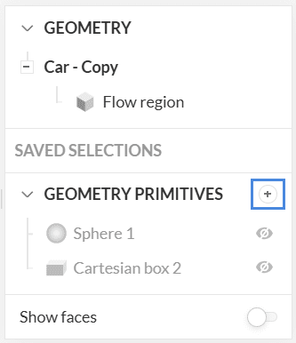
They can also be created by clicking the ‘+’ button next to Geometry Primitives under the scene tree.
Types of Geometry Primitives
Cartesian Box
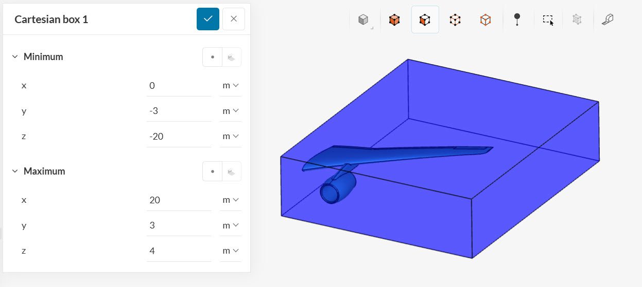
A Cartesian box is specified with the minimum and maximum box coordinates in the x, y, and z-directions. The figure below shows a cartesian box for a mesh region refinement.
Note
Geometry primitives can also be created using the pick method. Select the Pick from the viewer icon ![]() to choose a point from within the simulation domain which will act as the corresponding coordinate, for e.g. minimum coordinate for the cartesian box or the centre for the sphere geometry primitive.
to choose a point from within the simulation domain which will act as the corresponding coordinate, for e.g. minimum coordinate for the cartesian box or the centre for the sphere geometry primitive.
Sphere
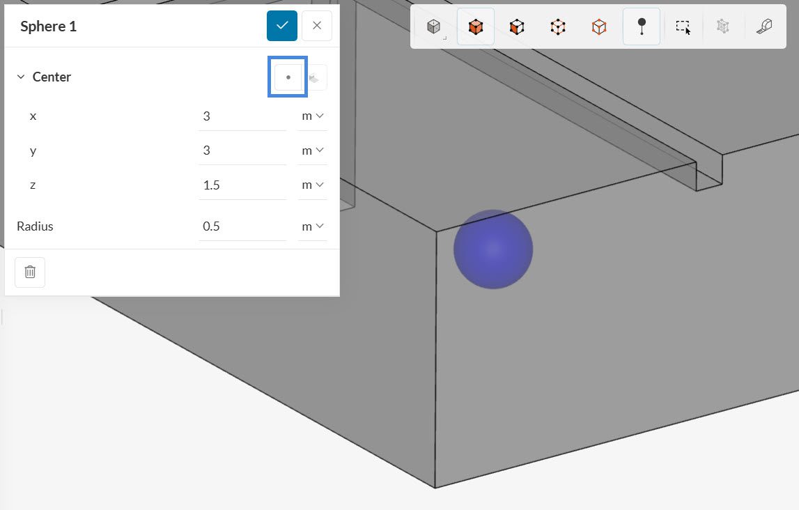
Spheres can be used for mesh refinements, spherical power sources, and passive scalar sources. To create a sphere, one has to specify its center coordinates, as well as the radius. “Pick from the viewer” option can be particularly useful to properly define the origin of the sphere as shown in Figure 4.
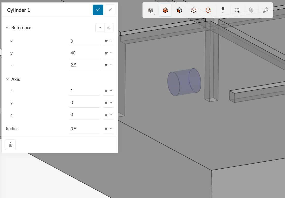
Cylinder
Cylinders are often used for mesh refinements. Another common application is to create momentum sources, which mimic the effects of a fan.
To specify a cylinder, the user needs to input a point of reference for the base of the cylinder. By adjusting the axis, one can determine the direction and length of the cylinder. Finally, the user should also define the radius for the cylinder.
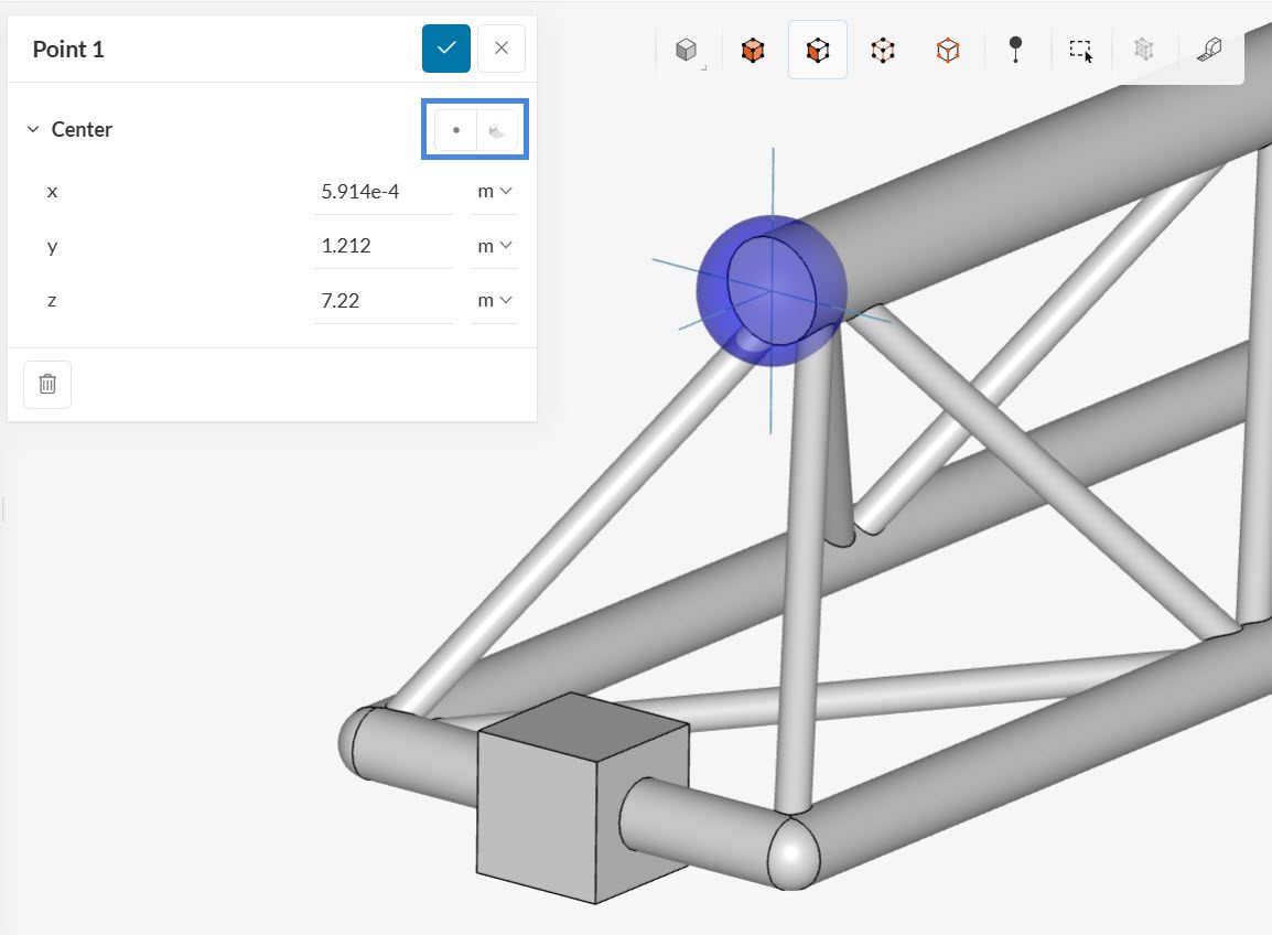
Point
Points are mostly used to create probe point result controls. A chain of points can be created to obtain a profile of the simulation variables across a line. The center coordinates are sufficient to set up a point geometry primitive.
Pick from the viewer and Pick center of selection options as shown in Figure 6 is particularly helpful to define probe points if the desired coordinates are not explicitly known in advance.
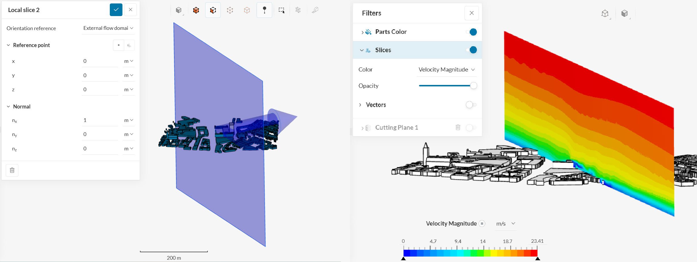
Local Slice
Local slices are used in the Pedestrian wind comfort (PWC) and Incompressible (LBM) analysis types. They are planes (2D) that are placed in the domain for data visualization. For more information about local slices, please check this page.
List of Applications
Find below a list of applications where geometry primitives can be used, as well as the available types:
- Volumetric refinement for a mesh (standard algorithm or hex-dominant algorithm): Cartesian box, sphere, and cylinder;
- Subdomains for initial conditions: Cartesian box, sphere, and cylinder;
- Momentum sources: Cartesian box, sphere, and cylinder;
- Porous media: Cartesian box and cylinder;
- Passive scalar sources: Cartesian box, sphere, and cylinder;
- Power sources: Cartesian box, sphere, and cylinder;
- Scalar transport result control: Point
- Result control: Point.
Last updated: September 30th, 2025
Did this article solve your issue?
How can we do better?
We appreciate and value your feedback.


