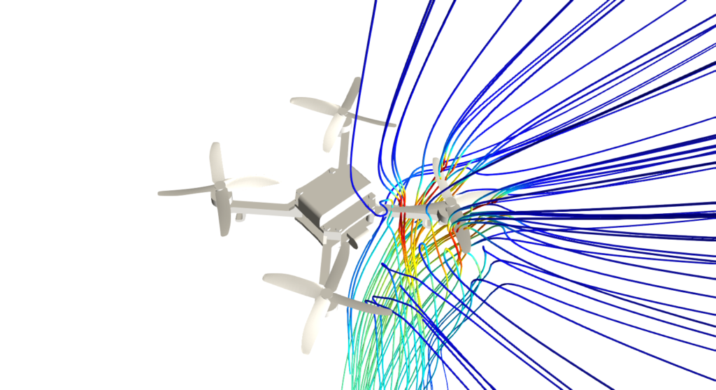
This article provides a step-by-step tutorial for the flow simulation around a drone using rotating zones (the propeller) using the moving reference frame (MRF) modelling technique.
This tutorial teaches how to:
- Set up and run an incompressible flow simulation
- Assign boundary conditions, material, and other models to the simulation
- Mesh the geometry with the SimScale standard meshing algorithm
- Set up a moving reference frame (MRF) rotating zone
The typical SimScale workflow will be followed:
- Prepare the CAD model for the simulation
- Set up the simulation
- Set up the mesh
- Run the simulation and analyze the results
1. Prepare the CAD model and Select the Analysis Type
First of all, click the button below. It will copy the tutorial project containing the geometry into your Workbench.
The following picture demonstrates what should be visible after importing the tutorial project:

1.1 Required CAD Preparation: Rotating Zones
You can see that there are two geometries in the imported project. The first one is called Drone and the second one is called Volume Region. The drone model shows the body with its four propellers and a cylinder surrounding the region that will rotate:
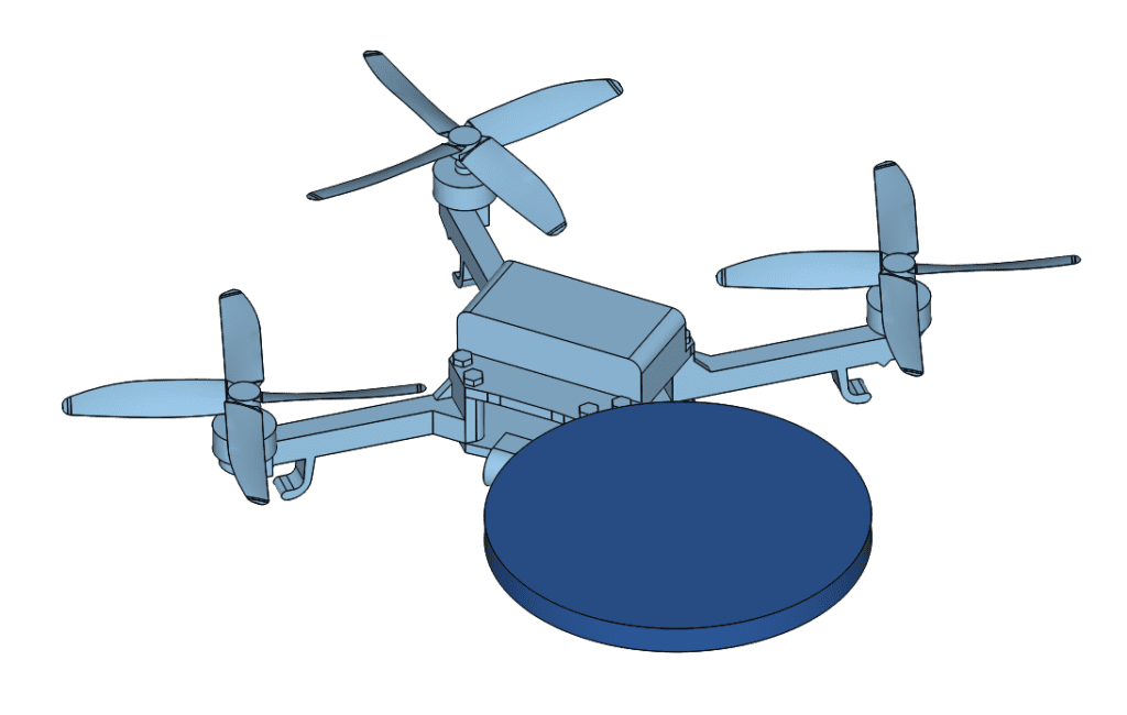
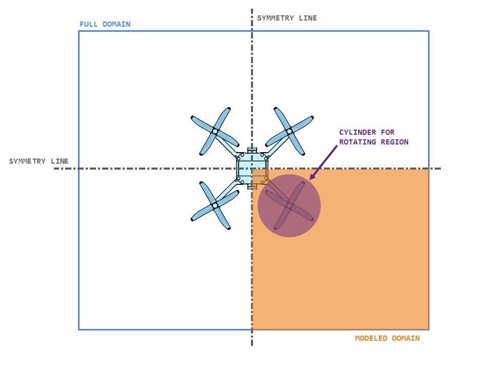
An important optimization in the drone simulation is achieved by noticing that this model has two planes of symmetry. This means that we can get away with modelling only one-quarter of the geometry. This is performed in the creation of the bounding box, which covers the desired quarter as shown in the following picture:
A crucial aspect of the modelling is the creation of the cylinder for the rotating region. This cylinder should cover (with some margin) the faces that will be included in the rotation model. The one used in our case covers the drone propeller, and can be found by having a closer look at the Drone Parts geometry:
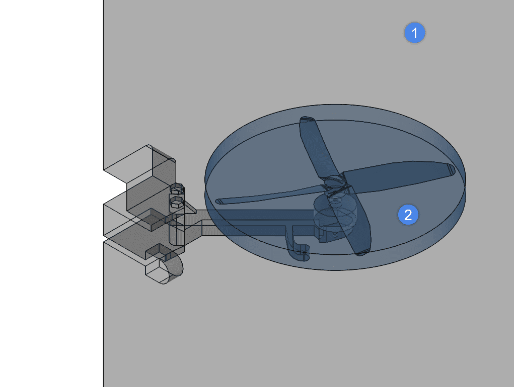
- The flow region (gray), which models the volume filled by fluid. Notice that it has a void representing the space occupied by the drone structure and propellers and that it uses the symmetry of the model as explained above.
- A cylinder covering the propeller (blue). This cylinder will be used to create the region of cells rotating and the MRF concept.
Tip
You can better visualize the internal faces by changing the render mode to translucent surfaces. Do this by using the top bar at the viewer.
Important
In case you want to model your drone or any external rotating geometry for that matter, you should always follow the modelling convention outlined in this section: a flow region volume with the removed bodies and a cylinder around the rotating region.
You can also create the flow region using CAD mode, or in your CAD following the instructions on this page.
1.2 Create Saved Selections
Saved Selections are groups of faces used for quickly applying boundary conditions or other assignments. Such selections are listed in the panel on the right side of the Workbench.
For example, the Volume Region geometry has a couple of pre-saved selections:
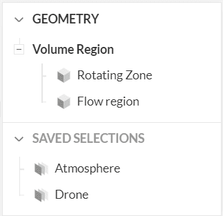
For the Volume Region geometry, please create a new saved selection for the symmetry planes, following the steps below:

- First, select the corresponding two faces from the viewer (notice these are the ones that intersect with the drone).
- Click the ‘+’ icon next to Saved Selections in the right-hand side panel.
- In the pop-up dialog that appears, name the selection ‘Symmetry’ and click on ‘Create new selection’.
1.3 Create the Rotating Zones Drone Simulation
Now we can start with the simulation setup. Follow the steps presented in the picture below to create a new simulation for our geometry:
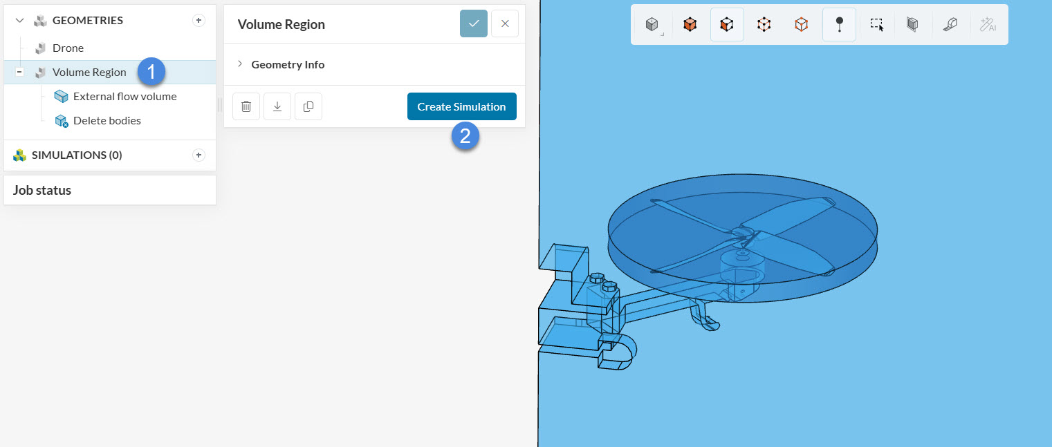
- Select the ‘Volume Region’ geometry from the left panel
- Click on the ‘Create Simulation’ button
At this point, the analysis type selection widget appears:
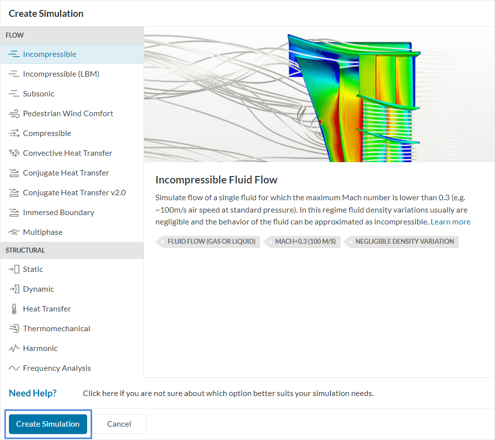
Choose ‘Incompressible’ and click on ‘Create Simulation’. A new simulation tree will appear at the left panel and a pop-up with the global simulation settings, which we will leave at the default values.
2. Set Up the Rotating Zones Simulation
2.1 Material Model
To define and assign a material, click the ‘+’ button next to Materials. Doing so, the SimScale material library will pop up. Select Air from the materials library and click Apply:

The material properties window will appear. Assign the Flow Region volume and accept the selection with the check-mark button.
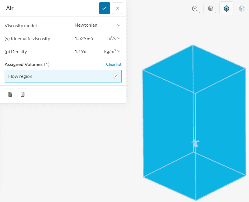
Please note that only the flow region receives a material definition -the Rotating Zone volume remains without an assignment.
2.2 Boundary Conditions
Now we will define the boundary conditions. To create a boundary condition, follow the steps shown in the picture below:
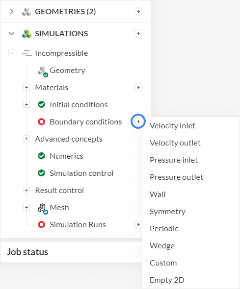
- Click on the ‘+’ button next to Boundary Conditions
- Select the proper type from the drop-down menu
- Set up the physical parameters and assigned faces in the pop-up dialog (not shown in the picture)
Now apply this process for the following boundary conditions:
a. Drone Surface
For the drone faces, a no-slip wall condition is used.
Create a new boundary condition by following the instructions in Figure 12 and selecting ‘Wall’. Now select the Drone saved selection to assign it to the boundary condition. You can also rename the boundary condition to ‘Drone’.
Leave all parameters as default, as shown in the picture:

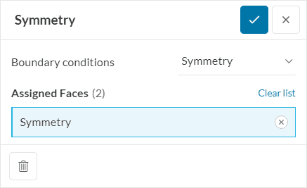
b. Symmetry Planes
For the symmetry planes, a ‘Symmetry’ boundary condition is used.
Create it according to the steps presented in Figure 12. Once the setup panel pops up, select the Symmetry saved selection that was created before for the assignment.
The setup should look as shown in the picture:
c. Atmosphere
For the faces open to the atmosphere, a custom boundary condition will be used. Follow the same procedure as before to create a custom boundary condition.
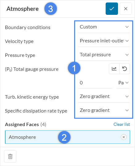
- As we do not know if the direction of flow at these faces will be inlet or outlet, it will allow the solver to automatically compute it. Therefore we select ‘Pressure inlet-outlet velocity’ for the (U) Velocity setup.
- Define ‘Total pressure’ for the gauge pressure option and assign ‘0’ Pa, which corresponds to atmospheric pressure.
- We set the turbulence quantities, Turb. kinetic energy and Specific dissipation rate to ‘Zero gradient’, so that the solver calculates them.
2.3 Propeller Rotation
To specify the rotating propeller in our model, a moving reference frame (MRF) rotating zone is employed. The following picture shows how to create it:
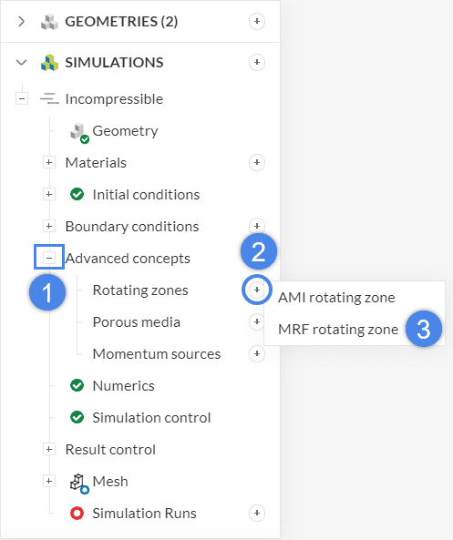
- Expand Advanced concepts.
- Click on the ‘+’ button next to Rotating zones.
- Select ‘MRF rotating zone’ from the list.
In the pop-up window, assign the Rotating Zone volume and set up the parameters as shown in the picture:
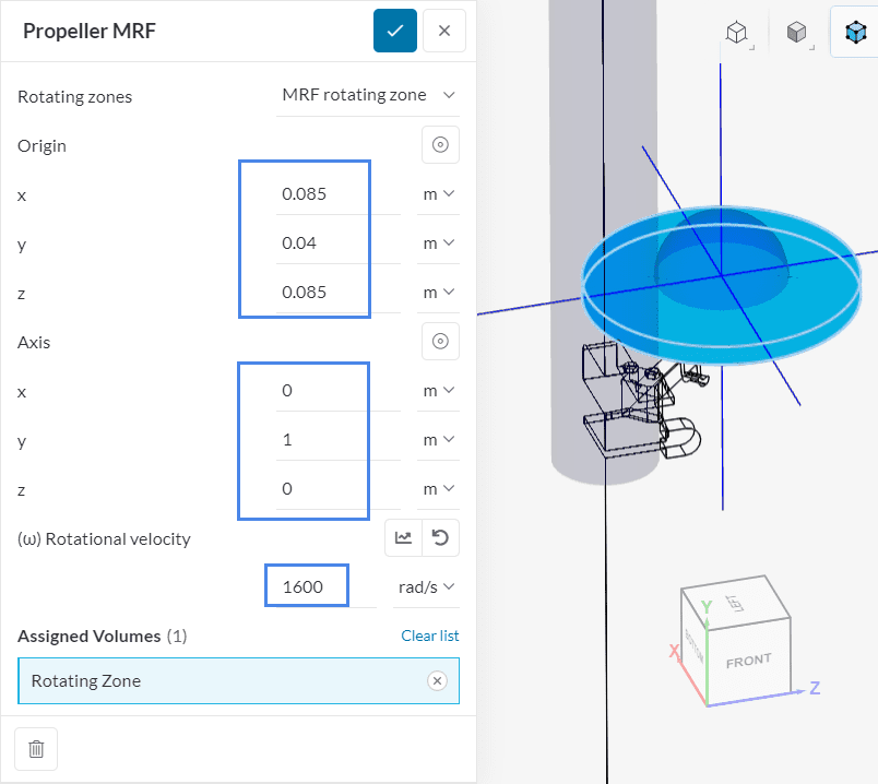
You can read more on the topic of MRF rotating zones at the corresponding documentation page:
2.4 Numerics and Simulation Control
For the numeric solver parameters, one parameter will be changed: The Number of non-orthogonal correctors. This will allow the solver to achieve a better solution for the tetrahedral mesh created by the SimScale standard mesher algorithm:
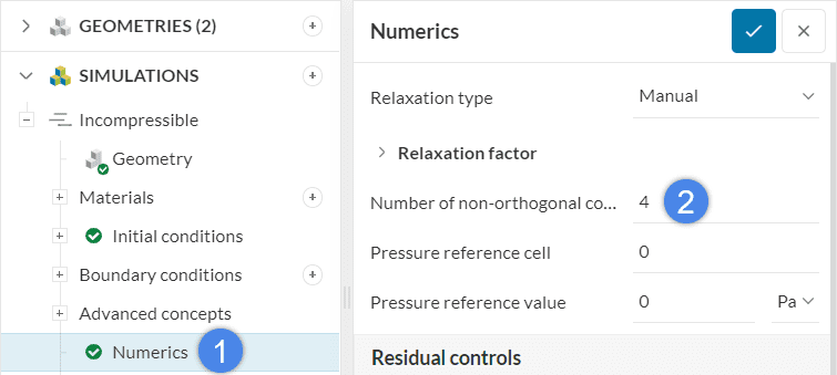
- Select Numerics from the tree at the left panel.
- Set the Number of non-orthogonal correctors to ‘4’.
The Simulation control parameters are left as default.
3. Mesh
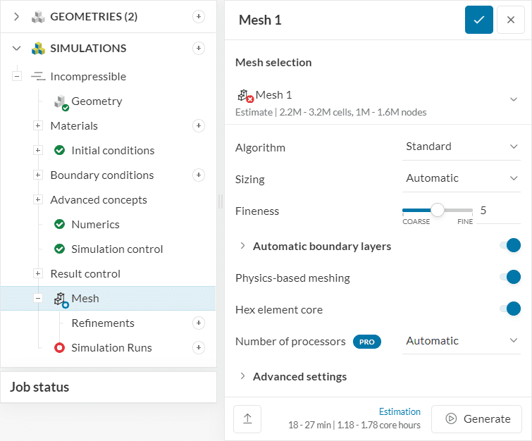
For the mesh setup, all settings are left as default, as we will make use of the SimScale standard mesh algorithm. You do not need to click Generate either, as the mesh will be computed as part of the simulation run:
Did you know?
It’s necessary to define cell zones in the mesh whenever we want to apply a specific property, such as a rotating motion, to a subset of cells.
The standard mesher algorithm automatically creates the necessary cell zones whenever Physics-based meshing is enabled. Since we are using physics-based meshing in this tutorial, the algorithm will take care of the cell zone definition.
If you are using a different mesher, you can learn alternative ways to define a cell zone on the rotating zones documentation page.
4. Start the Rotating Zones Simulation
Now that the simulation setup is complete, a new simulation run can be created to perform the computation. To do so, click the ‘+’ button next to Simulation Runs at the left panel. In the pop-up window, give a proper name to the run and click ‘Start’:
This computation takes around 30-40 minutes to be completed. If you can’t wait to see the results, at the end of the article you will find a link to the completed version of the project.
5. Post-Processing
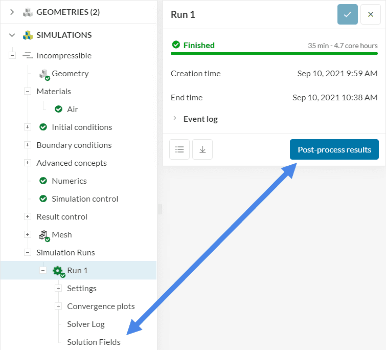
After the simulation is finished, access the post-processor by clicking the ‘Post-process results’ button or ‘Solution Fields’ under your run.
5.1 Surface Visualization
One of the most important things to observe in the drone is the pressure distribution on the surfaces of the drone. Follow the steps below to show pressure on the surfaces of the drone:
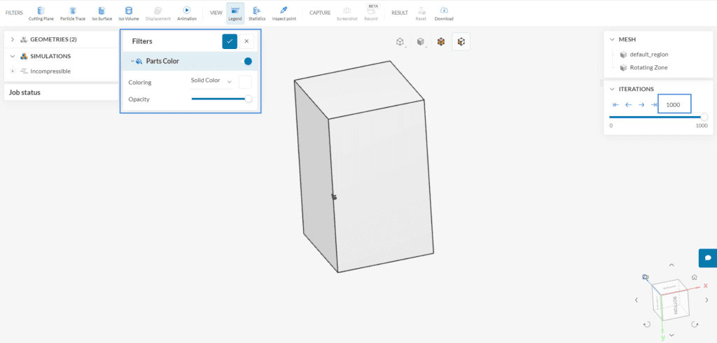
- Make sure that you are at the last timestep of the simulation and no filters are applied.
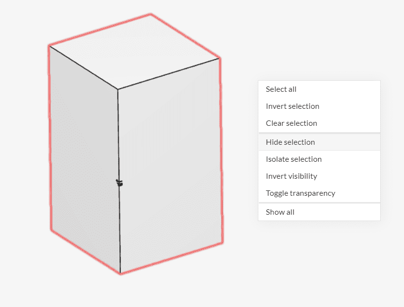
- Hide the walls surrounding the drone by selecting them, right-clicking on the post-processor, and choosing ‘Hide selection’.
- Change the Coloring to ‘Pressure’ in for the Coloring of the Parts Color to show the pressure distribution on the drone. To improve the visualization, you can also hide the Rotating Zone volume by clicking on the ‘eye’ icon.

- The scale range is automatically set to the minimum and maximum pressure values in the domain. You can adjust the scale range to more representative bounds if required.
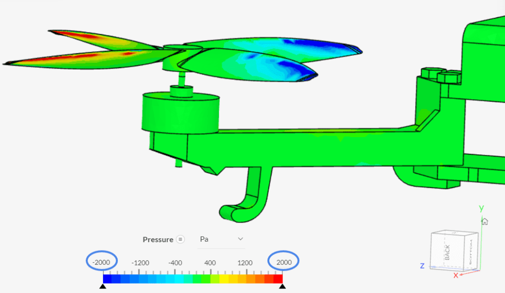
As you can see from Figure 25, the highest pressures are on the bottom of the blades, which is due to the air pushed down by the propellers. Since the upper part of the blades experiences low-pressure levels, this generates a lift force, countering gravity.
5.2 Particle Traces
We will continue showing the airflow through the propellers of the drone by using streamlines. See the steps below to create them:

- Select a ‘Particle Trace’ filter from the top ribbon. This will lead to the settings for the particle trace setup
- Make sure that the Pick Position icon
 is activated
- Select the bottom of the drone
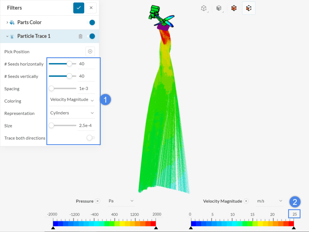
Next, configure the streamlines so that they are more representative. Change the #Seeds horizontally and #Seeds vertically to ’40’, so that there are 40 origin points vertically and horizontally. Change the Spacing and Sizing to ‘1e-3’ and ‘2.5e-4’, respectively.
To observe only the streamlines downstream from the drone, you can disable Trace both directions. Furthermore, adjust the upper bound of Velocity Magnitude to ’25’ \(m/s\) to make the visualization more representative.
After creating the traces, it is possible to animate them with an ‘Animation’ filter:
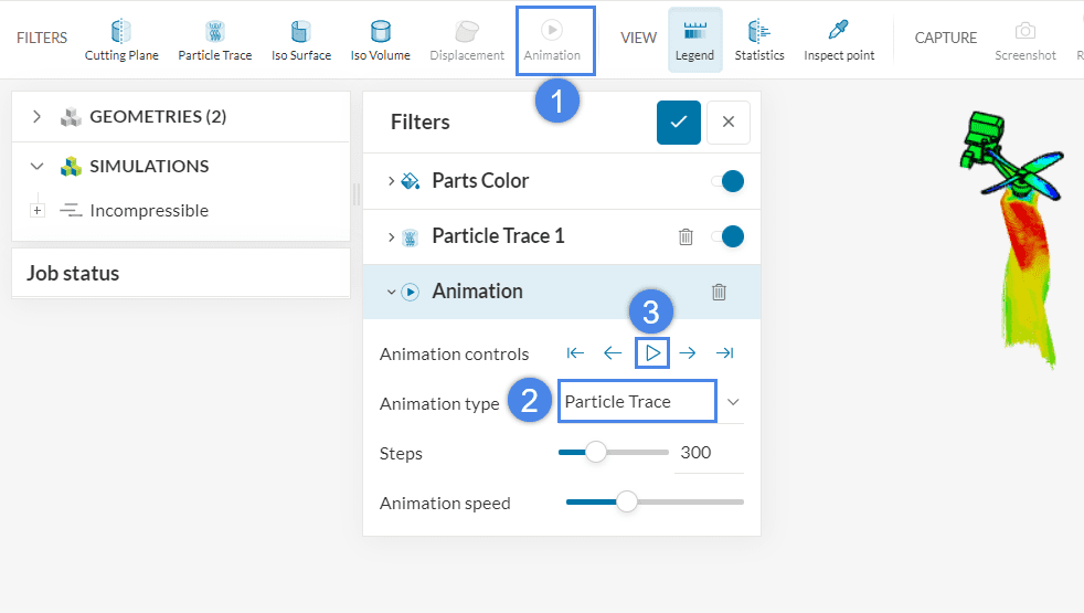
- Create an ‘Animation’ filter
- Make sure that the Animation type is ‘Particle Trace’
- Set the animation to run
The resulting animation looks like the video below:
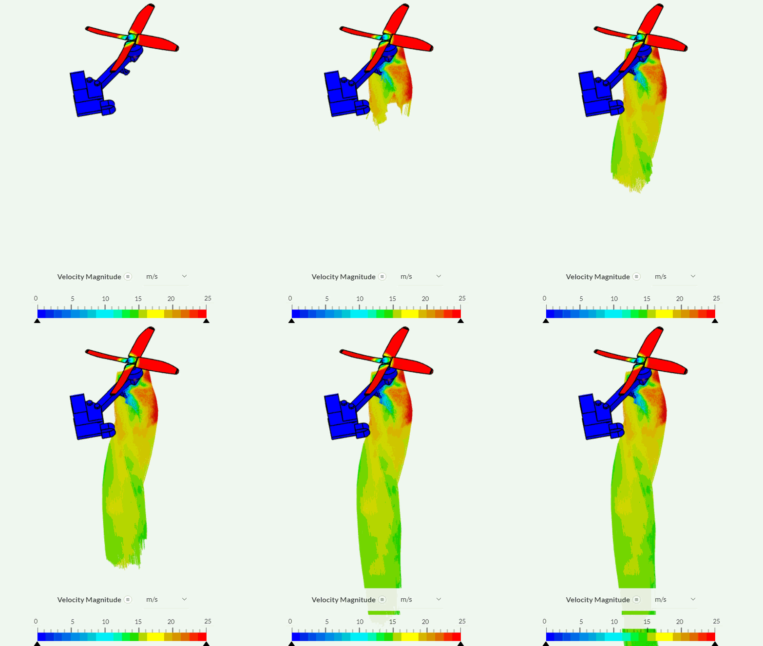
From the animation above, it can be seen that the flow velocity accelerates when going through the drone and creates a swirl due to the rotating movement of the propellers.
5.3 Cutting Plane
To better comprehend the velocity contours around the blades, create a cutting plane by following the steps below:

- Select a ‘Cutting Plane’ from the top ribbon. This will open a window with settings
- Change the Position to 0 meters, 0.035 meters, and 0 meters in x, y, and z. Furthermore, change the Orientation to the y-axis
- Enable the Vectors slider and change the Coloring of the vectors to a black ‘Solid color’. The Scale factor of the vectors should be ‘0.03’ with a Grid Spacing of ‘0.005’. Project the vectors onto the plane by enabling Project vectors onto Plane
From Figure 29, we can see that the velocity is higher within the propeller rotating zone. Air being pushed towards the propeller center can also be observed as a result of pressure difference and it moves in rotation according to the movement of the propellers.
You can analyze your results further with the SimScale post-processor. Have a look at our post-processing guide to learn how to use the post-processor.
Congratulations! You finished the drone with a rotating zone tutorial!
Note
If you have questions or suggestions, please reach out either via the forum or contact us directly.