When performing a simulation with rotating parts, such as pumps and turbines, we need to use rotating zones. This requires some additional steps to prepare the CAD before importing the model into the SimScale Workbench.
In short, a CAD model for simulations with rotating zones needs to contain one flow volume region and one additional volume per rotating zone. The rotating-zone volume must overlap the fluid region. This article outlines the best practices that users should follow to prepare their CAD models.
Important
It is possible to generate rotating zones in SimScale or in a CAD software. For demonstration purposes, we are going to showcase the workflows in SimScale and Onshape. (Onshape is not a part of SimScale)
Please note that, as far as CAD preparation goes, multiple workflows will lead you to the same result. This article does not intend to be exhaustive: it only shows one of the possible workflows.
Approach
The most important requirement when you prepare the CAD for a simulation involving rotating motion is the rotating zone: a cylindrical volume surrounding all rotating parts. For information regarding the setup of a rotating zone in SimScale, please visit this documentation page.
Below, you will find examples showing the workflow to prepare the CAD model for a simulation with rotating zones for internal and external applications. Examples are a drone, a water pump, and a wind turbine.
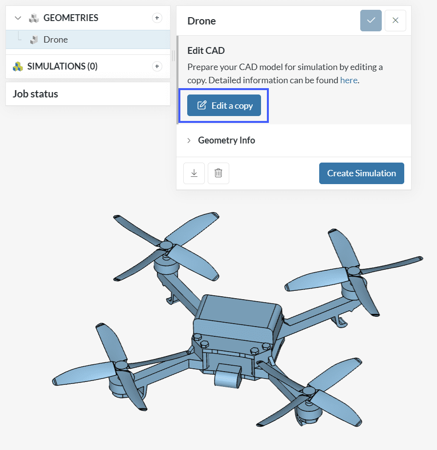
Example 1: Drone (SimScale)
This example features the geometry from the drone simulation tutorial. The geometry initially contains the drone propeller and the arm. Using CAD Edit the flow volume region and the rotating zone can be created within the SimScale environment without having to leave the platform.
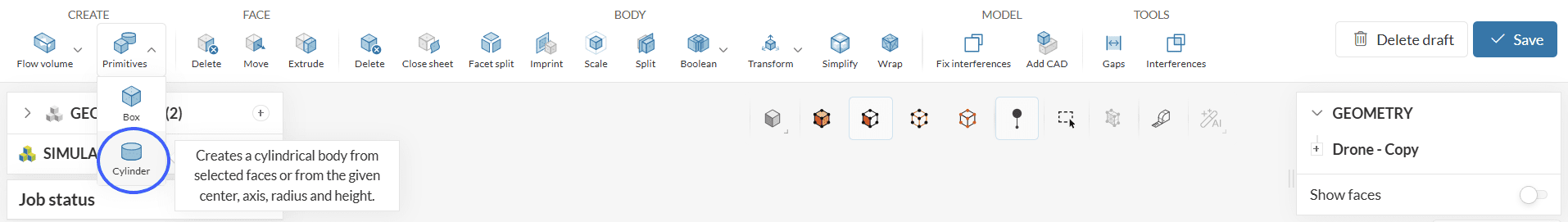
The Primitives Cylinder operation in CAD Edit allows the creation of cylindrical volumes that can be used when dealing with simulation domains having rotating zones. There are two methods to create cylinders: Custom and From faces.
When using the Custom method, the center of rotation, axis of rotation, radius, and height of the cylinder need to be specified by the user.
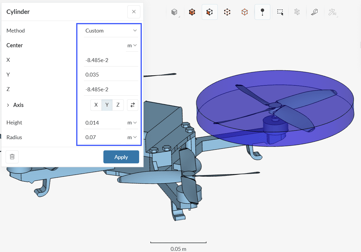
The Custom approach requires global coordinates to be provided for the creation of the cylinder. In case you don’t have those readily available, the From faces approach might be preferred.
When using the From faces approach to create a cylinder, the user needs to select the Faces which should be covered by the cylinder:
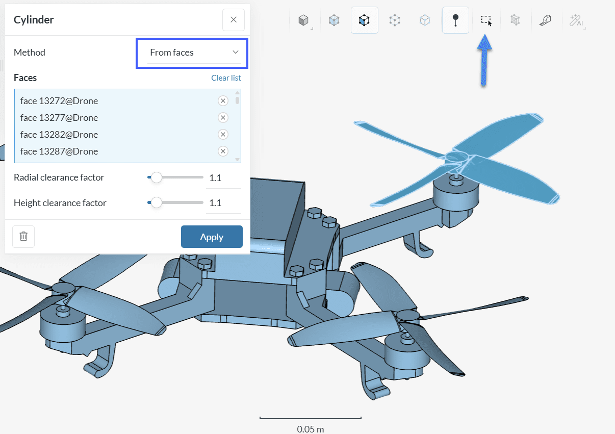
With this approach, a cylinder that envelops all selected faces is created. Furthermore, a Clearance factor is applied, ensuring that the cylinder is slightly larger than the assigned faces. For simulations involving rotating machinery, a Clearance factor of 1.1 is recommended.
As a result of the Cylinder operation, a brand new volume is created:
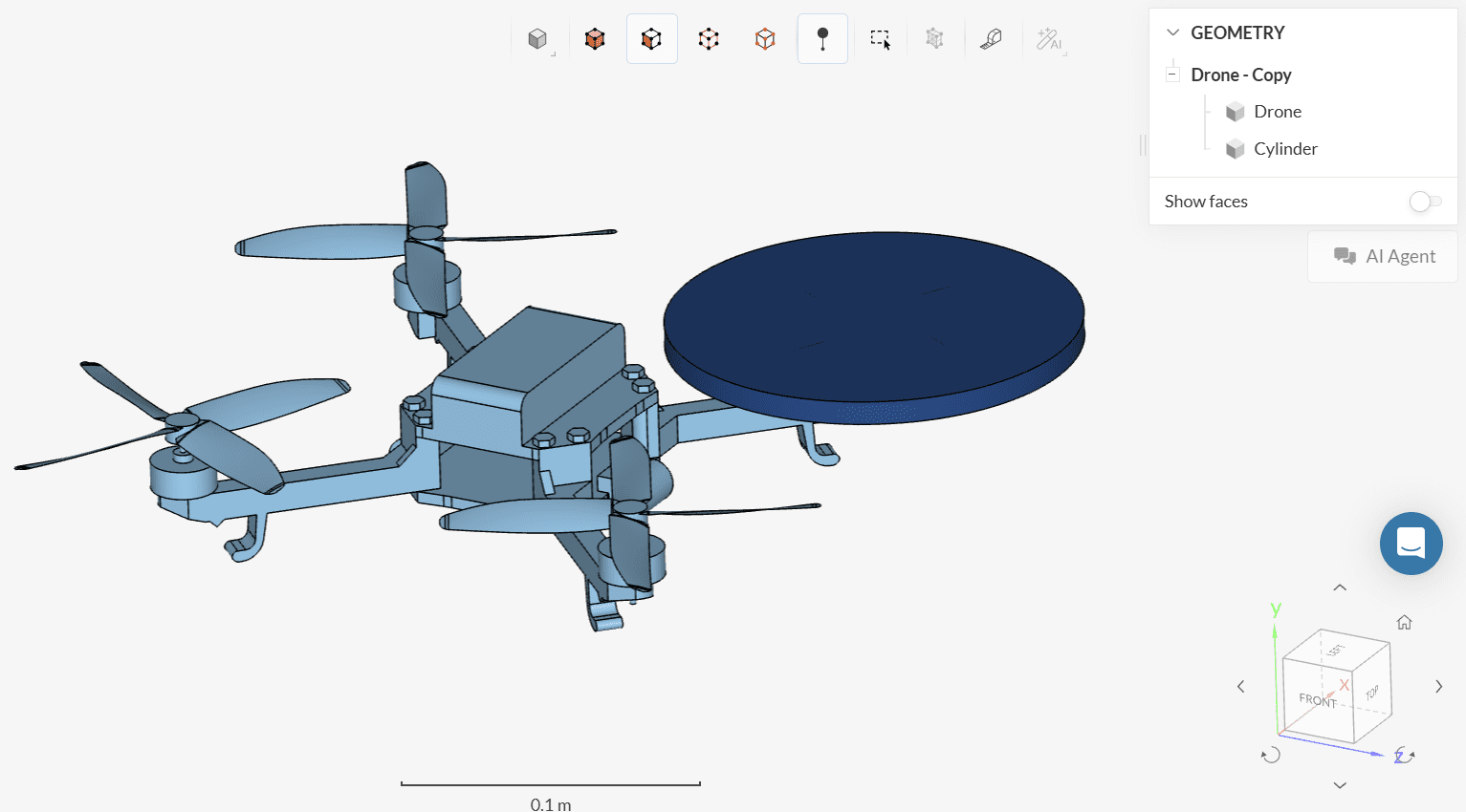
Creating a rotating zone using CAD Edit is suited when dealing with cylindrical rotating regions. For more complex blade shapes and orientations refer to the following examples.
Example 2: Wind Turbine (SimScale)
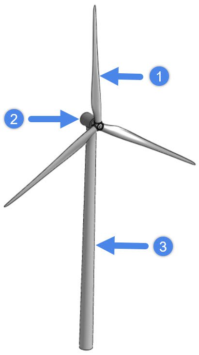
In this example, a wind turbine geometry containing only the solid turbine parts is used as a starting point.
Upon bringing this model to SimScale, we can enter the CAD Edit environment to perform the following operations:
- Create a cylinder to represent the rotating zone
- Create a flow region for the external aerodynamics simulation
- Delete the solid parts of the wind turbine
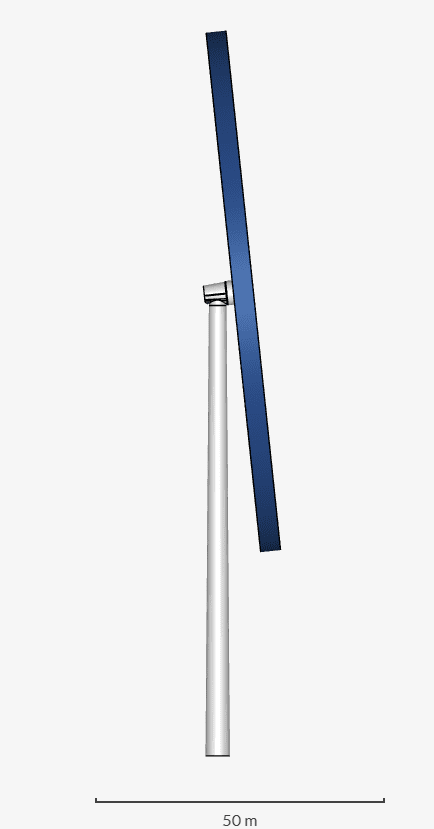
The blades from this geometry are at an angle. With the From faces method for the Cylinder operation, the algorithm will automatically generate a rotating zone with the correct angle:
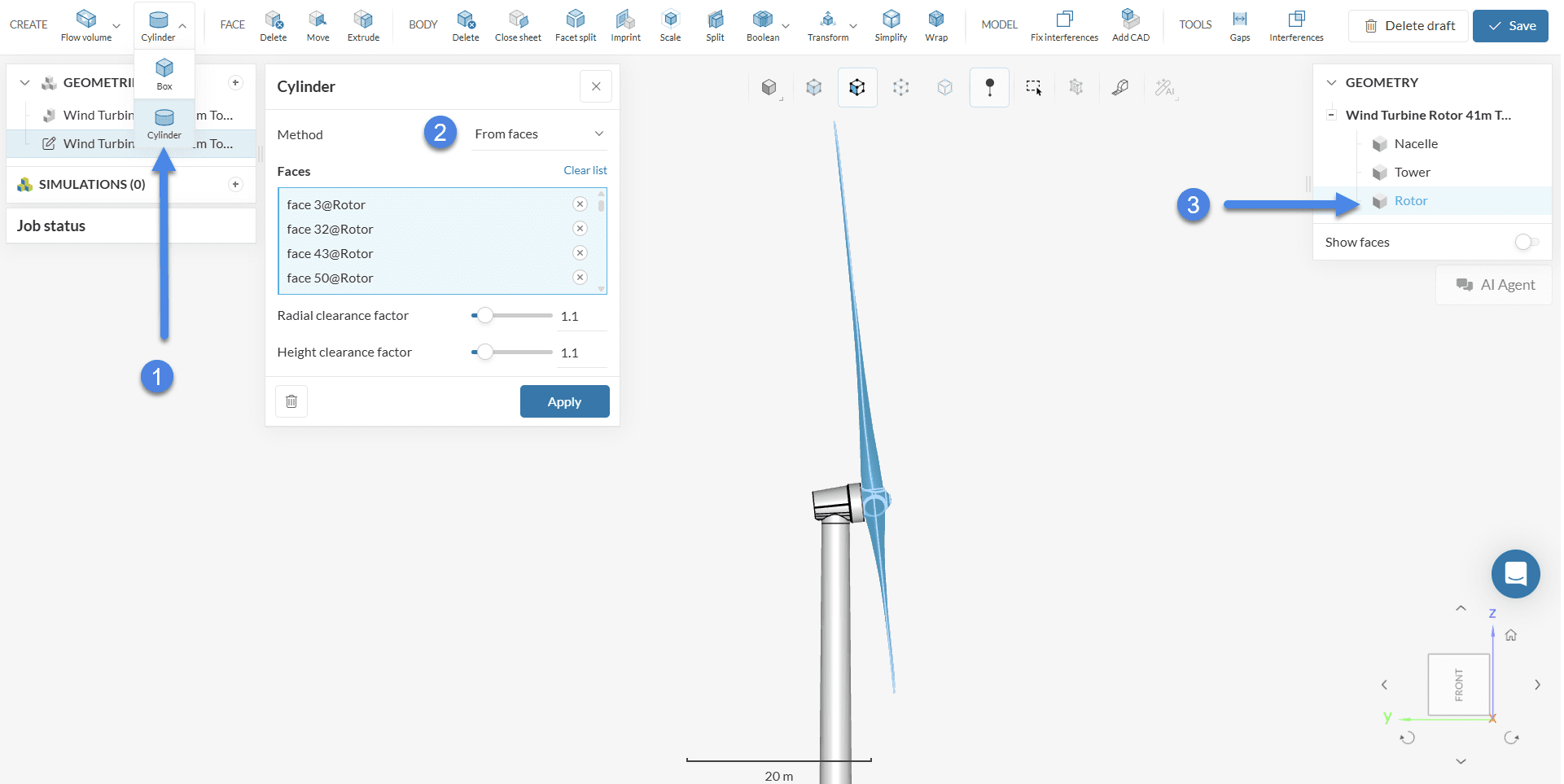
An easy way to quickly select the rotor faces is by having an explicit volume for the rotor (separate from the rest of the geometry). The result will be an angled rotating zone:
After creating the rotating zone volume, the next step is to generate a flow region. In this case, an External Flow Volume operation is the best option:
Finally, before clicking Save to export the new geometry back to the Workbench as a copy, the solid parts (tower, nacelle, and rotor) first need to be deleted using a Delete Body operation:
After deleting the solid parts, the CAD model will be correctly constructed for a simulation involving rotating zones.
Did you know?
In a CAD model that is correctly prepared for simulations with rotating zones, the flow region will contain the negative of the solid parts. Note that the solid parts (e.g. the rotor blades) should not be part of the final geometry.
Example 3: Water Pump (Onshape)
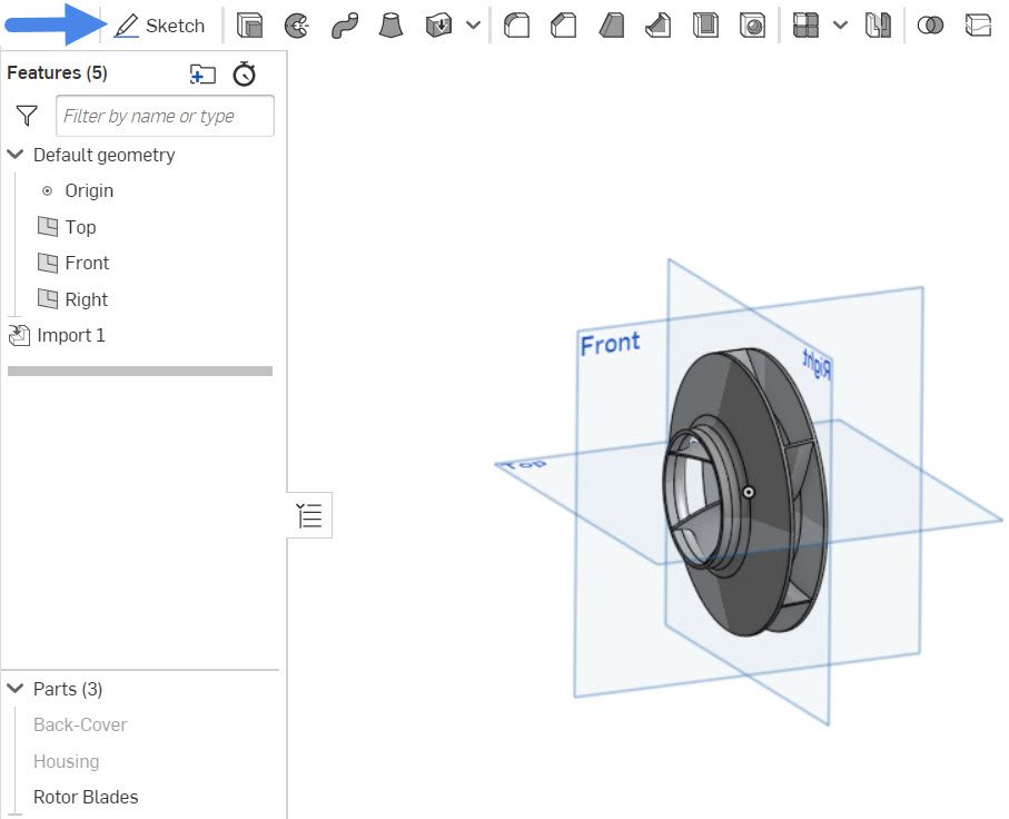
This example features the geometry from the water pump tutorial. The initial pump model contains the rotor blade, housing, and a back cover. Water enters the pump through the front inlet and leaves through the top outlet.
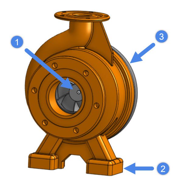
In the CAD tool, before importing the model to SimScale, we need to create a rotating zone around the rotor blades. Note that the rotor blades volume is centralized at the origin. This will make the next steps much easier to follow.
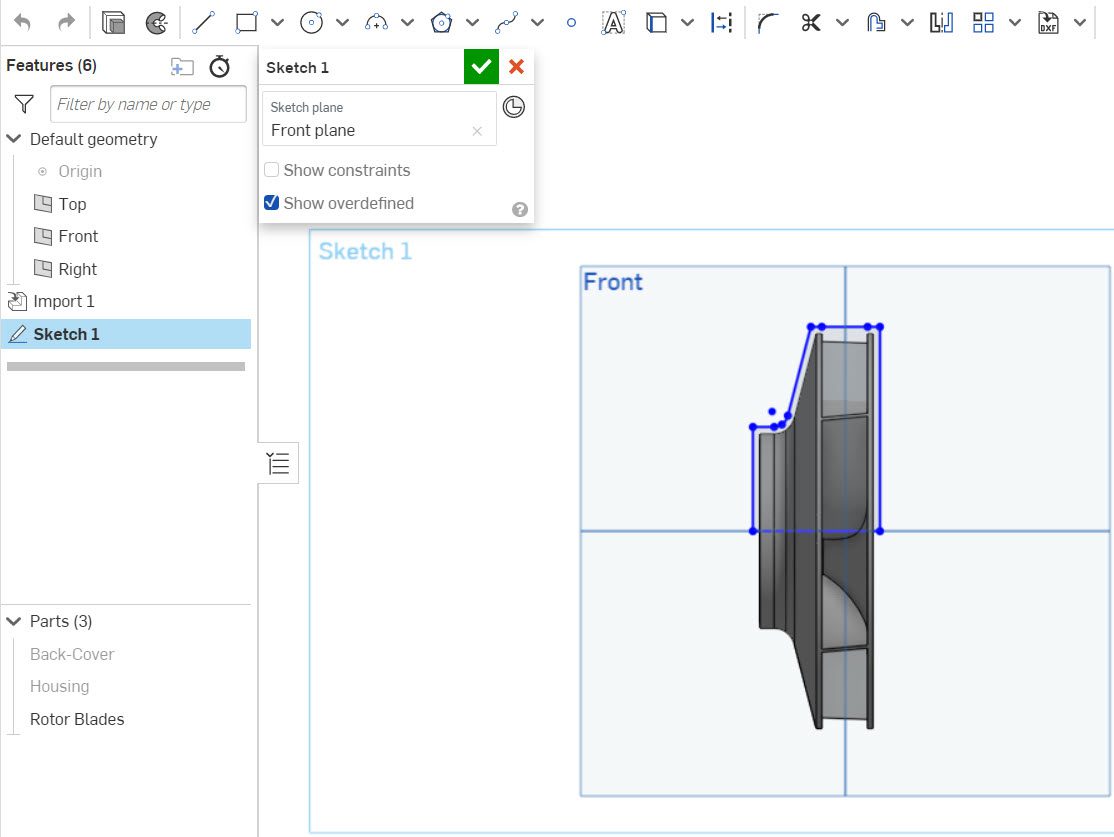
The first operation consists of creating a Sketch, using one of the planes at the origin. In this case, we will use the Front plane:
Now, we can use sketch tools to draw a profile for the rotating zone, which will be revolved afterward. Note that the profile should be slightly larger than the rotor in all directions. As a rule of thumb, you can make the rotating zone extend further than the blades in all directions by a distance of \(0.05D\), where \(D\) is the diameter of the blades.
After accepting the sketch, we are ready to use the Revolve operation to create the rotating zone volume, with the following steps:
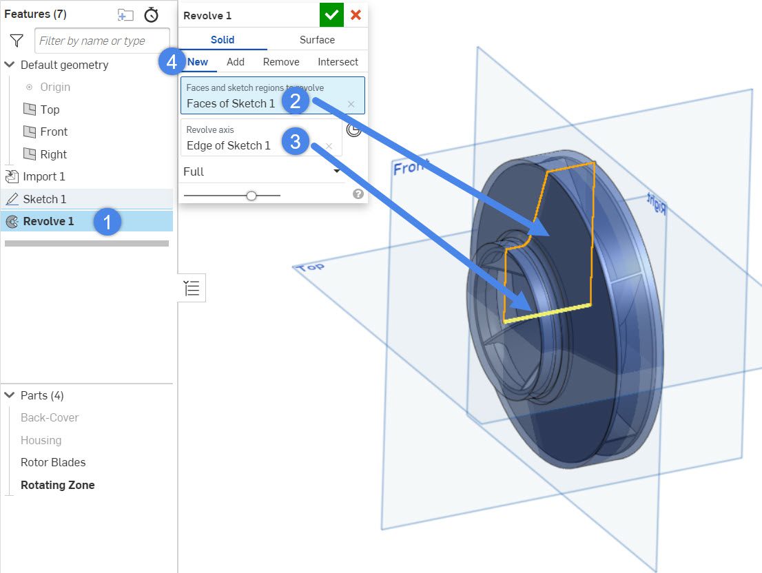
- Create a ‘Revolve’ operation
- Select the faces of the sketch as the profile to revolve
- The revolve axis will be the baseline of the sketch, which goes through the point (0, 0, 0)
- Make sure that you are creating a ‘New’ volume in this operation
At this point, the geometry consists of 4 parts: the back cover, the housing, the rotor blades, and the rotating zone. This geometry can be imported to SimScale for further CAD preparation. To see all CAD import options, please refer to this documentation page.
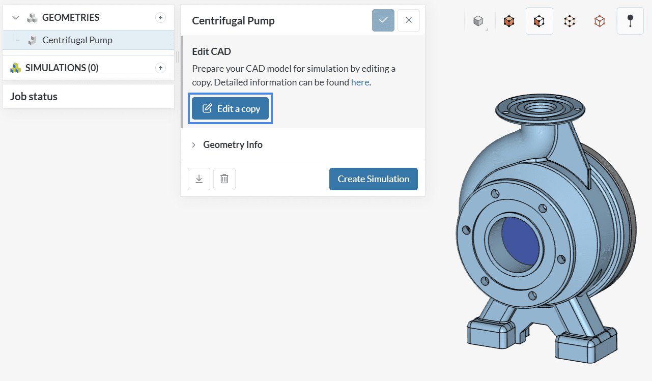
CAD Edit
The geometry is not yet ready to run a CFD simulation. We need to create a flow region, and also delete the solid parts of the domain.
Both of these operations can be performed in SimScale’s CAD Edit:
Within CAD Edit, we have two main objectives:
- Create an internal flow region
- Delete all solid parts from the geometry
Therefore, the first step is to select an ‘Internal flow volume’ operation, and follow the steps below:
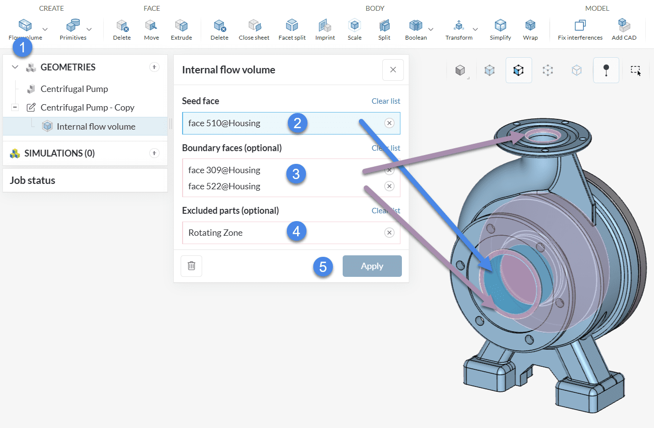
- Create an ‘Internal’ flow volume extraction operation
- As Seed face, assign one internal face that will be in contact with the flow region
- Under Boundary faces, assign the boundary faces around the openings. Make sure to check this article if you are unsure about the boundary faces of your geometry
- Assign the Rotating Zone volume in the Excluded parts tab
- Press ‘Apply’ to run the operation
At this point, one volume named Flow region is created in the scene tree on the top right. We are now ready to delete the unnecessary parts of the geometry.
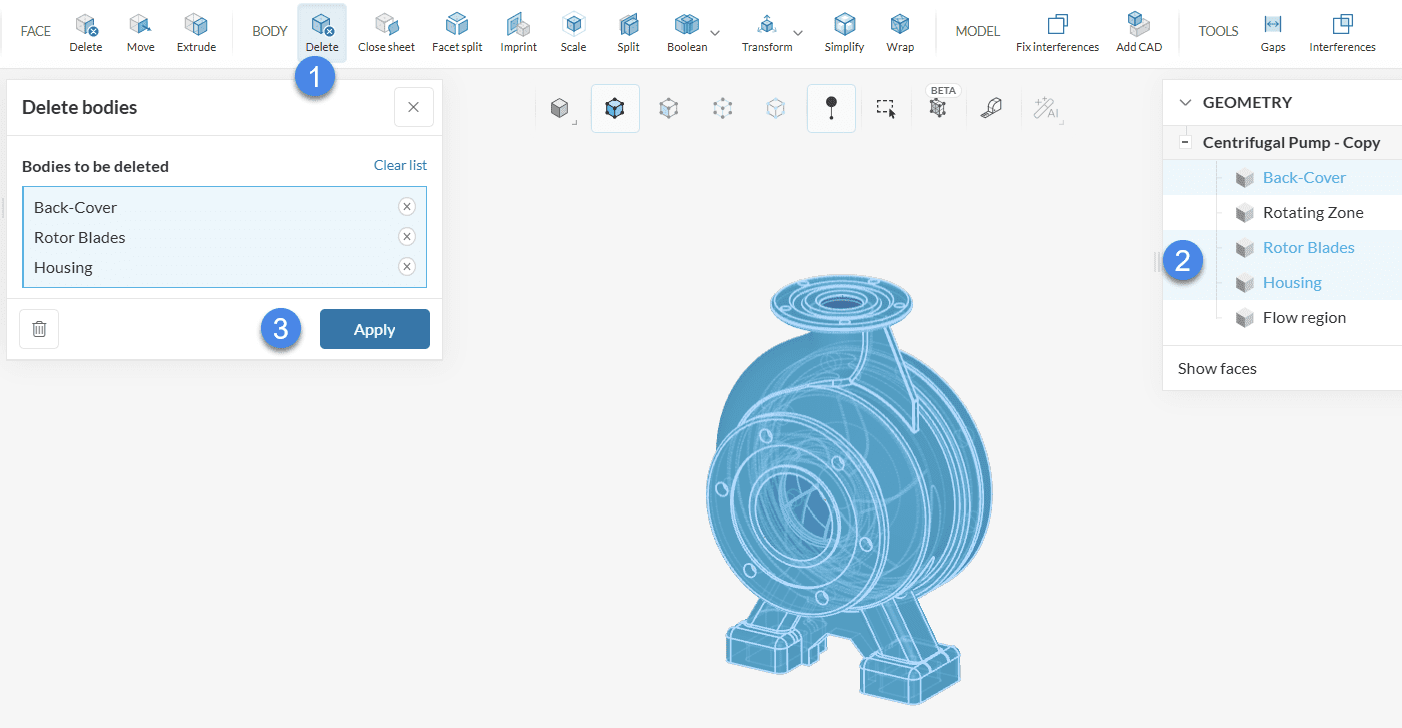
- Pick the ‘Delete’ operation under BODY
- Select the rotor blades, the housing, and the back-cover volumes. Note that two volumes remain unselected: the flow region and the rotating zone
- Hit ‘Apply’
Before exporting this model to the Workbench, we can also extend the inlet and outlet faces, which is a good practice for simulations with pumps. The Move face operation can be used for this purpose:
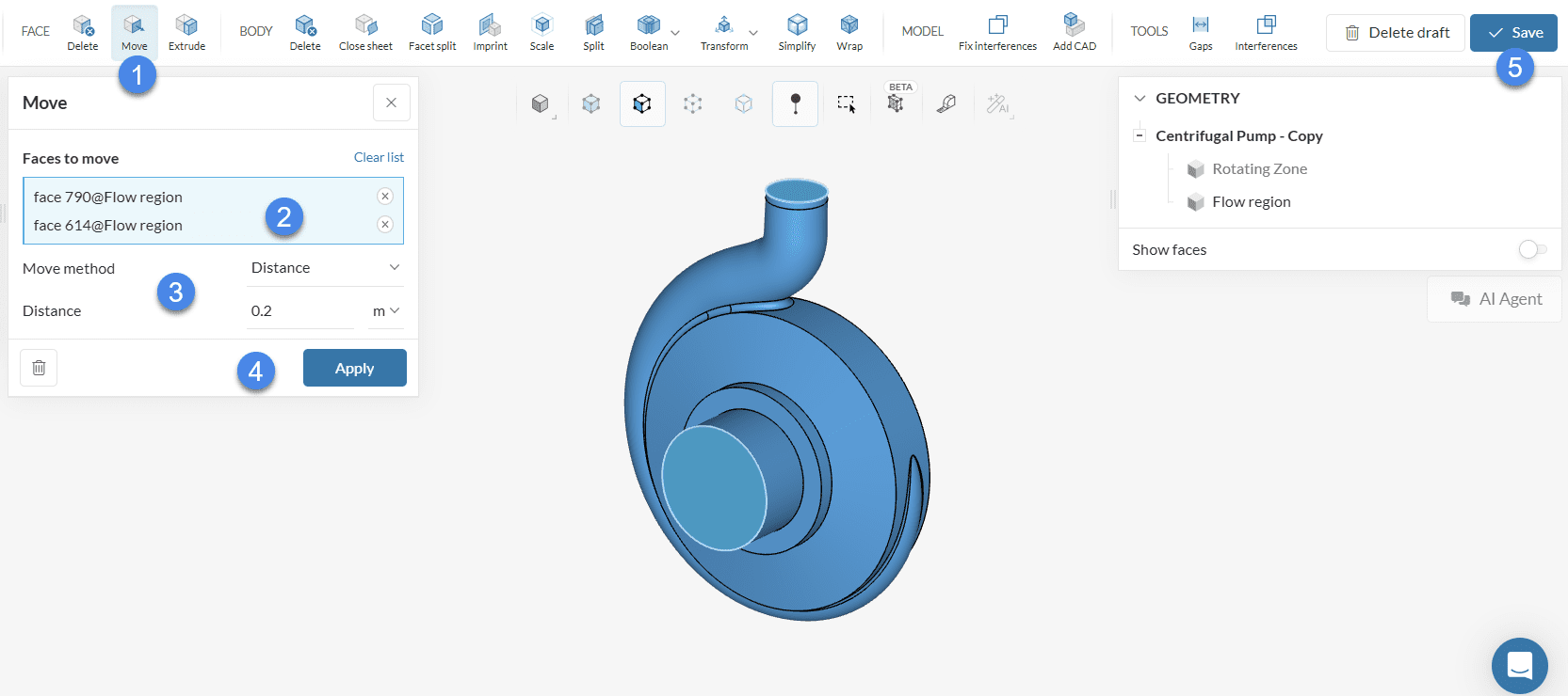
- Select a ‘Move’ operation
- Select inlet and outlet faces
- Set the Move method to ‘Distance’, with an appropriate Distance of interest
- Hit ‘Apply’ to run the operation
- Click on ‘Save’ to export the model to your Workbench
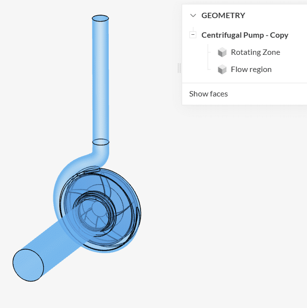
This geometry is correctly constructed for simulations with rotating zones in SimScale.
Example 4: Wind Turbine (Onshape)
In this external aerodynamics example, the same wind turbine model will be used, but this time the MRF rotating zone will be constructed in Onshape.
The easiest way to prepare the CAD model is by sketching a cylinder, which will be used to construct the rotating zone:
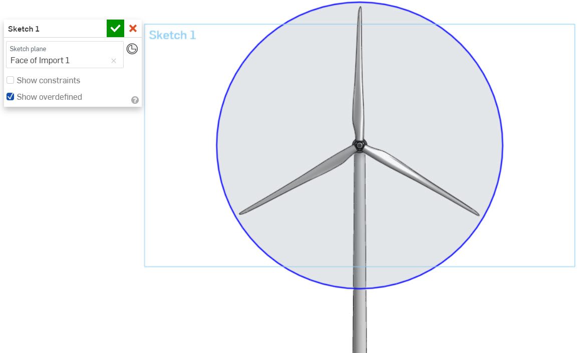
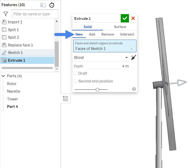
After creating the initial sketch, we are ready to extrude the MRF rotating zone as a new part. In this step, it’s important that the rotating zone fully envelops the rotating parts:
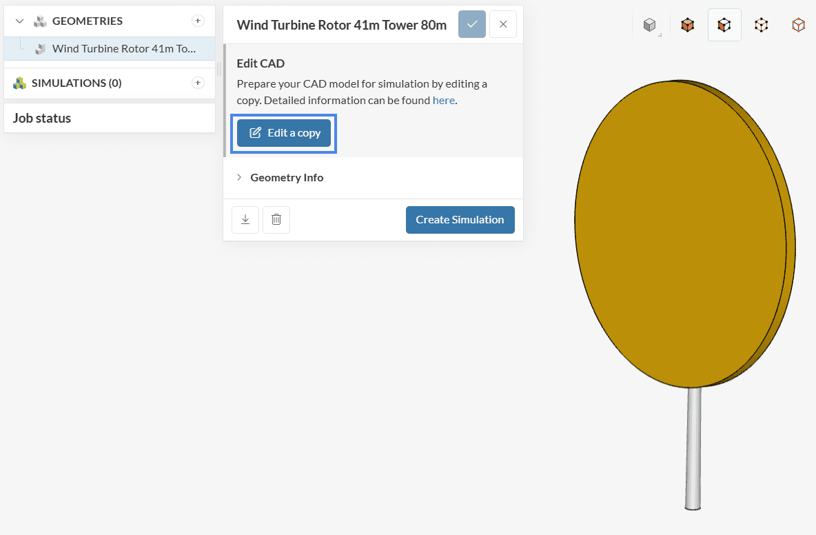
At this point, you can rename the rotating zone volume appropriately, and the model is ready to import to SimScale.
CAD Edit
Once in SimScale, it’s necessary to perform a couple of operations before using the geometry for a simulation. The objectives from this stage are:
- Generating the flow domain for the simulation
- Deleting the unnecessary solid parts from the model
Both of these operations can be performed within the CAD Edit environment, which can be accessed from the Geometries tab:
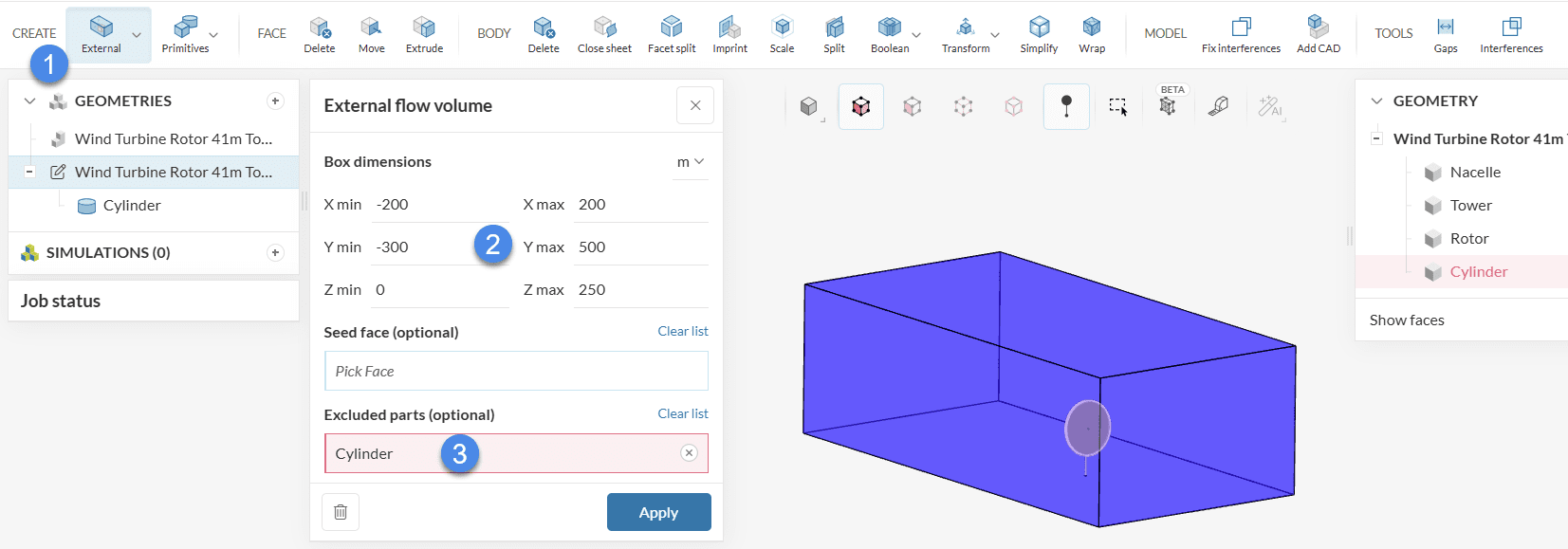
Initially, we are first interested in creating an external virtual wind tunnel. The image below shows the steps:
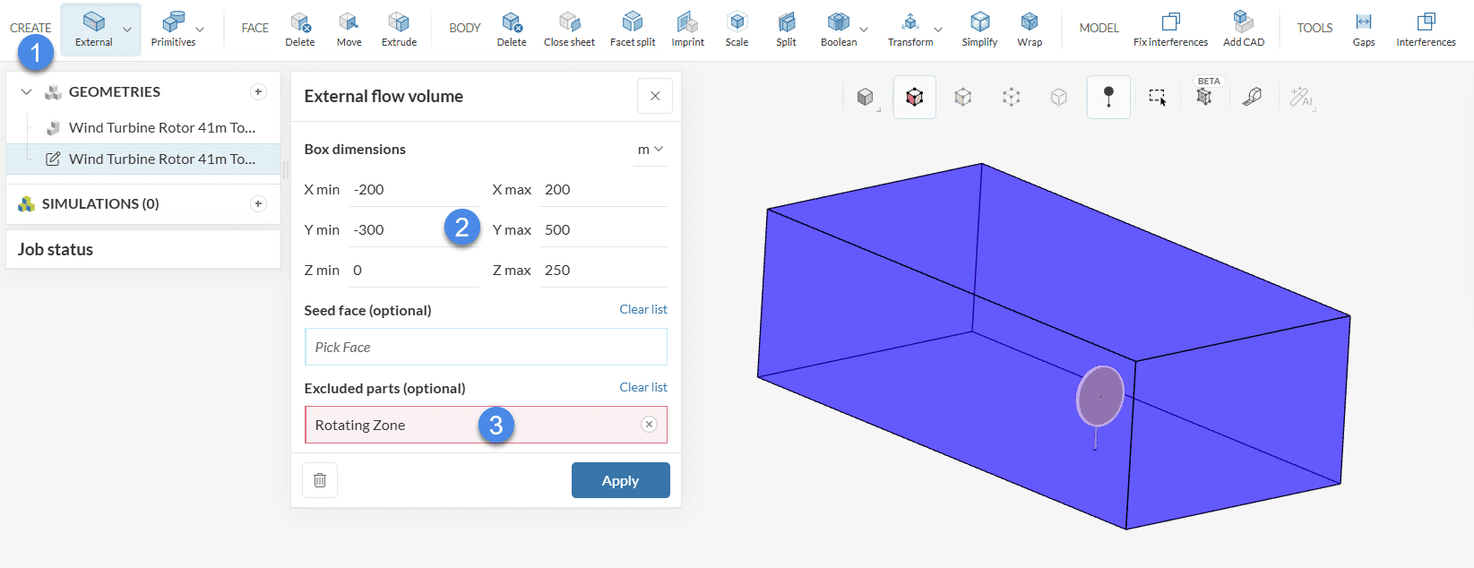
- Select an ‘External’ flow volume operation, which will construct an enclosure
- Define the enclosure dimensions according to your geometry and wind direction
- Exclude the Rotating zone volume that was created in your CAD tool from the operation. This will ensure that the rotating zone is correctly constructed for the simulation
- Hit ‘Apply’ to run the operation
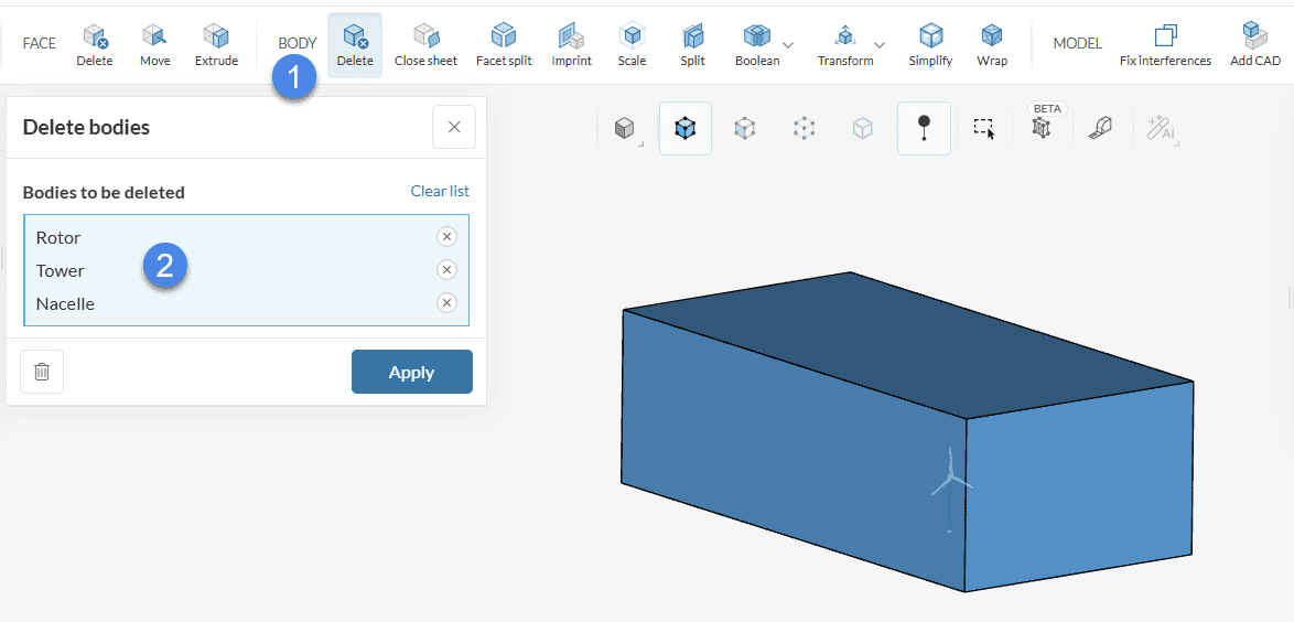
At this point, the geometry is almost ready to run a simulation. To avoid multi-region mesh errors, it’s necessary to delete the solid parts from the geometry. In CAD Edit, we can proceed as follows:
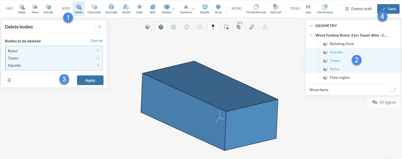
- Pick the ‘Delete’ operation under BODY
- Select the rotor blades, the nacelle, and the tower. Note that two volumes remain unselected: the flow region and the rotating zone
- Hit ‘Apply’
- Click ‘Save’ to export the new CAD version to your Workbench
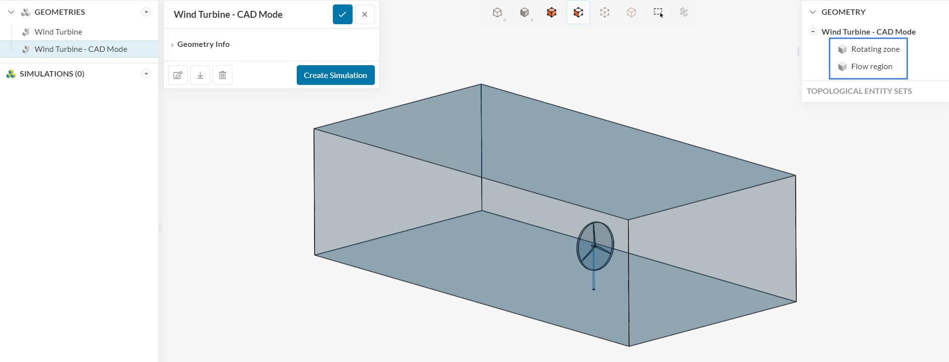
Now that we have only the two necessary volumes to run simulations with rotating zones, we can proceed to creating a simulation. During the simulation setup, assign the fluid material only to the flow region. Do not assign a material to the rotating-zone volume.
Note
If none of the above suggestions solved your problem, then please post the issue on our forum or contact us.


