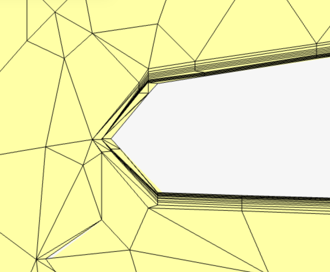
Boundary layer settings control mesh refinement close to solid walls in a CFD simulation. The boundary layer is the thin near-wall region where the flow velocity changes rapidly from zero at the wall to the surrounding flow velocity. Because large velocity gradients occur in this region, the near-wall mesh can strongly affect wall shear stress, pressure loss, separation, drag, and heat transfer.
Boundary layer options in SimScale
Boundary layers can be added in two ways: through Automatic boundary layers in the main mesh settings or through an Inflate boundary layer refinement. Automatic boundary layers apply near-wall layers more generally, while an Inflate boundary layer refinement gives more local control on selected faces.
In SimScale, the relevant settings include the number of layers, first layer size, total layer thickness, growth rate, and layer gradation control. Choose these settings based on the intended wall treatment, then check the result using y⁺, which describes the non-dimensional distance of the first cell from the wall.
This article gives a practical overview of how to use these boundary layer settings in SimScale and when to adjust them during mesh setup.
Automatic Boundary Layers
Define Automatic boundary layers in the main mesh settings. They apply globally to the relevant wall faces in the mesh. This option is useful when most surfaces use the same near-wall mesh strategy.
The available inputs include the number of layers, first layer size, overall thickness, and layer gradation control. The (y+)-based example below explains these settings in more detail. It is typically a good starting point when the geometry does not require different boundary layer settings on specific faces.
Inflate Boundary Layers (Refinement)
An Inflate boundary layer refinement applies boundary layer settings to selected faces. Use this option when certain surfaces need different near-wall resolution.
When you assign an Inflate boundary layer refinement to a face, its settings override the Automatic boundary layer settings on that face.
Choosing Settings based on y+
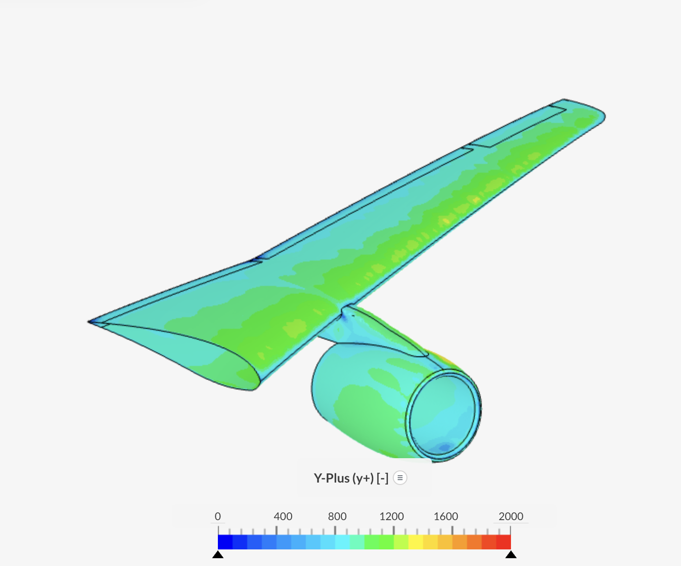
Choose the boundary layer settings based on the intended wall treatment. For wall-resolved simulations, place the first cell very close to the wall, commonly targeting y+ < 1. For wall-function approaches, place the first cell farther from the wall, commonly targeting 30 < y+ < 300.
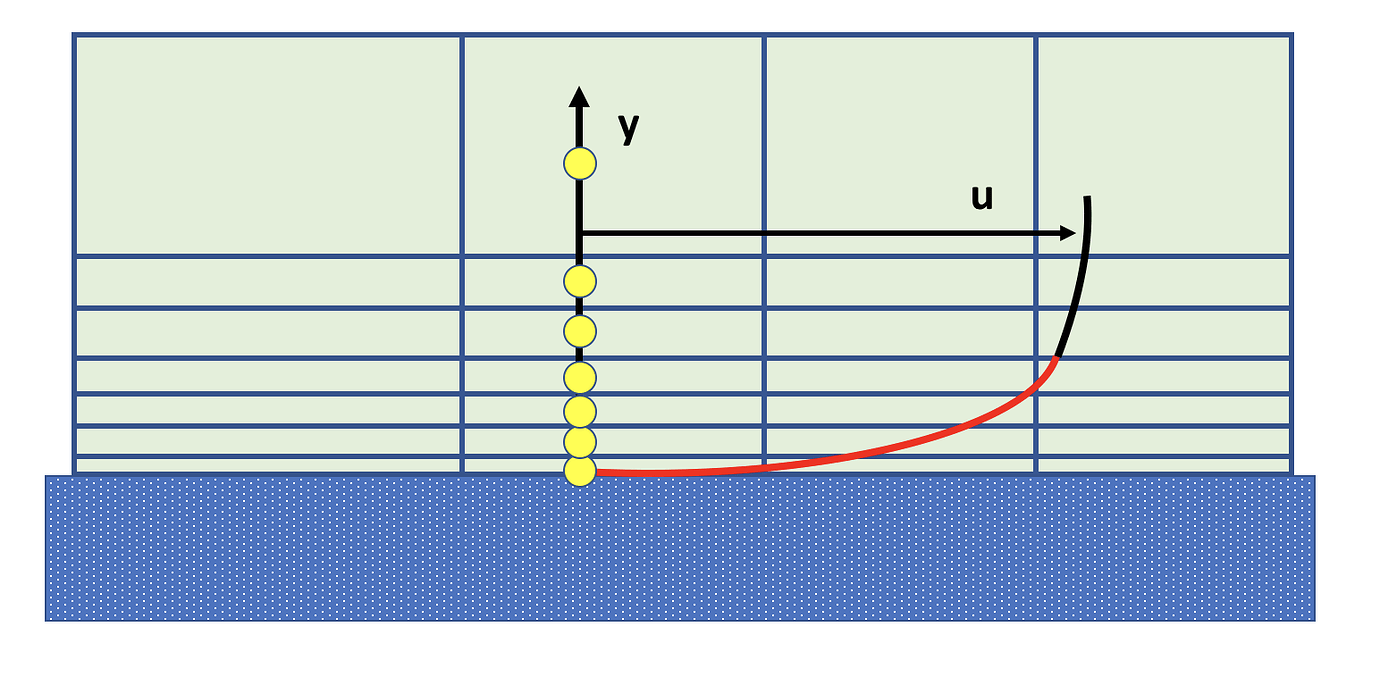
The y+ target mainly affects the First Layer Size, which represents the thickness of the first near-wall layer. A smaller first layer size reduces y+, while a larger first layer size increases y+. If the required first layer size is not known, estimate it using the y+ Calculator.
Choose the Layer gradation control option based on the information available:
- Specify growth rate is useful when the layer expansion ratio is known.
- Specify first layer thickness is useful when the first layer size is known from a y⁺ estimate.
- Specify first layer and total absolute thickness is useful when both the near-wall resolution and total boundary layer height need to be controlled.
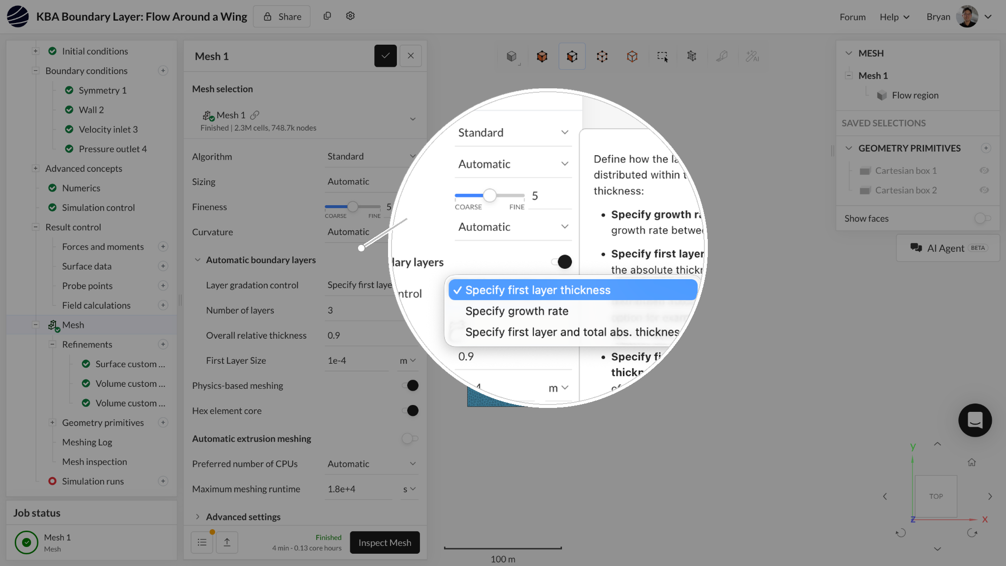
As a rule of thumb, growth rates are often set between 1.1 and 1.5. Lower values give smoother layer transitions but require more layers. The number of layers is commonly around 7–12, although fewer or more may be needed depending on the flow physics and wall treatment. Treat these values as starting points, not fixed rules.
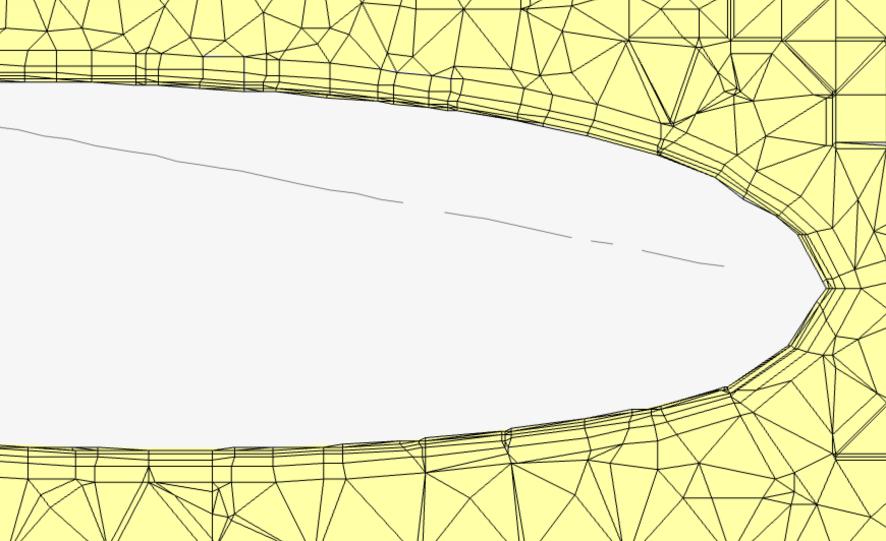
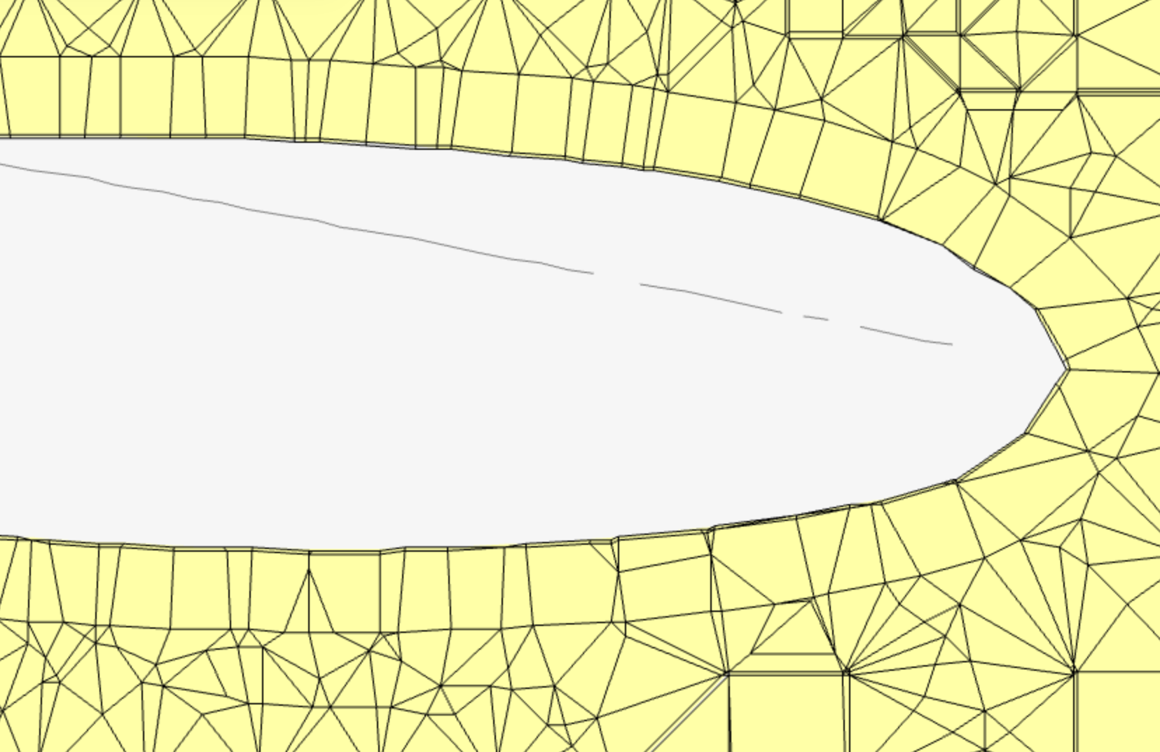
After generating the mesh, inspect the boundary layers visually. The layers should follow the wall smoothly and remain continuous along the surface. Poor boundary layer meshes may show distorted, collapsed, or missing layers, especially near sharp features, narrow gaps, or complex surface transitions.
Checking y+ After the Simulation
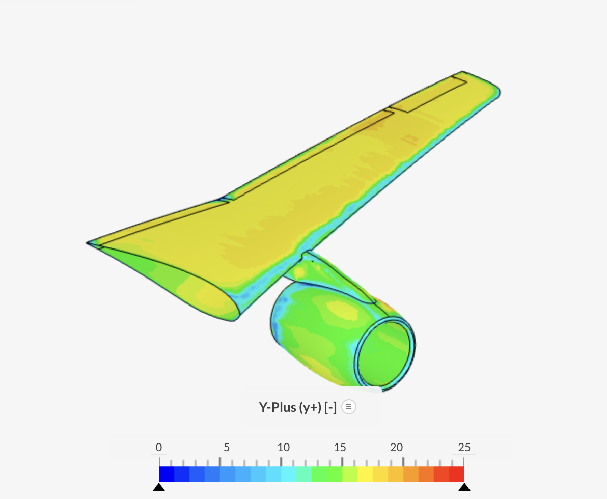
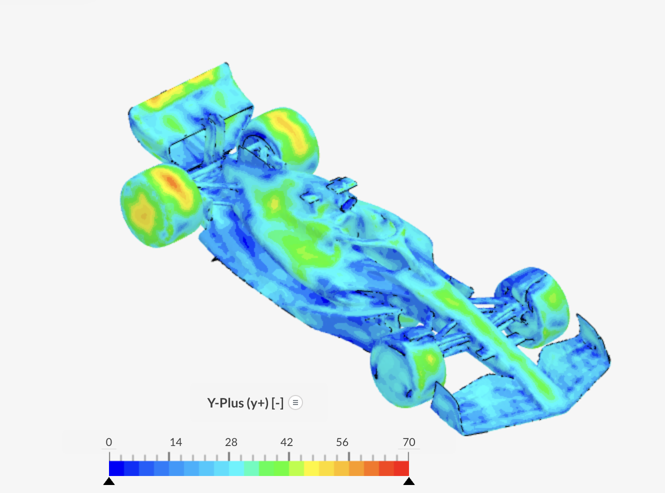
Before running the simulation, make sure Turbulence field calculations are added under Result control, so the y+ field is available in post-processing. After the simulation is complete, check the y+ field on the relevant wall surfaces. Localized high y+ values may indicate that the first layer size is too large in those regions. To fix this, reduce the first layer size globally or apply an Inflate boundary layer refinement locally.
Common Issues
Locally high y+ values
Possible cause: The first layer size is too large in regions with high wall shear, such as leading edges, narrow gaps, sharp corners, or moving walls.
Potential fix: Reduce the first layer size globally or apply an Inflate boundary layer refinement locally.
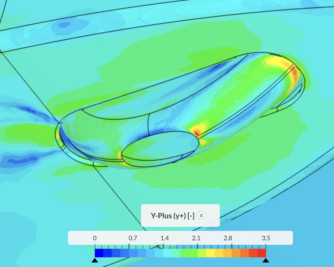
y+ is outside of intended range
Possible cause: The boundary layer settings do not match the selected wall treatment.
Potential fix: Adjust the first layer size based on the target y+ range.
Boundary layers are missing on some faces
Possible cause: Layer generation may fail near small gaps, sharp features, or complex geometry.
Potential fix: Improve the surface mesh, reduce the overall thickness, or simplify problematic geometry.
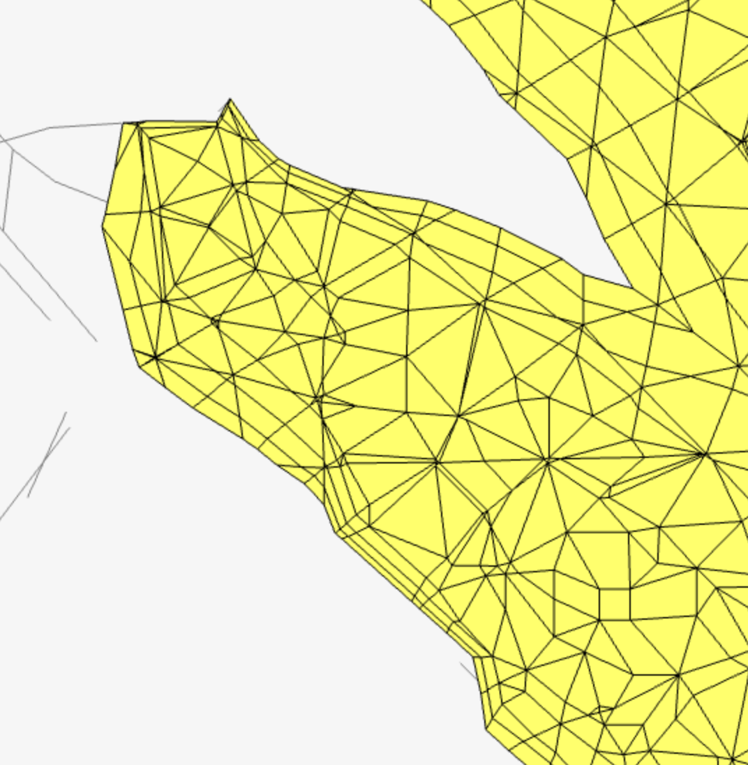
Boundary layers are distorted or collapsed
Possible cause: The overall thickness is too large for the local geometry.
Potential fix: Reduce the overall thickness or use local settings on selected faces.