What is Valve Flow Coefficient?
In fluid dynamics and valve design, the valve flow coefficient \(C_v) is essential for comparing different valve models and brands, reflecting the flow rate at a given pressure drop. It is crucial in designing valve systems that require precise control of fluid movement, making it fundamental for engineers and designers.
In this article, we explore what the valve flow coefficient is, covering its theoretical aspects, practical applications, and how SimScale’s cloud-native CFD simulation platform enhances the understanding and application of \(C_v\) in real-world scenarios.
What is \(C_v\)?
The valve flow coefficient is the flow capacity of a valve. It describes the valve’s efficiency in allowing the flow of fluid through it. This makes it a vital indicator of a valve’s performance. \(C_v\) is essential for ensuring that the chosen valve will meet the specific requirements of a system, including flow rate, pressure, and the nature of the fluid being controlled. A higher valve flow coefficient indicates a greater flow rate at a given pressure drop, which is crucial in applications where high flow efficiency is needed. A higher valve flow coefficient also often means better energy efficiency [1].
One of the most significant advantages of the valve flow coefficient is its role in standardizing valve performance metrics. It allows for a straightforward comparison between different valves, regardless of brand or model. This standardization simplifies the selection process for engineers, enabling them to choose the most suitable valve for their specific application based on a universally understood criterion.
The valve flow coefficient value is versatile and applicable to various types of fluids, including liquids and gases. However, it’s important to note that the flow coefficient of a valve will vary depending on the type of fluid it is controlling. The viscosity, density, and flow characteristics of the fluid all influence the value of the valve flow coefficient, making it crucial to consider these factors when selecting a valve for a particular application.
How to Calculate the Valve Flow Coefficient?
The valve flow coefficient equation can be calculated for different types of valves using the following general equation:
$$ C_v = Q \sqrt{\frac{SG}{\Delta P}} $$
Here, \(Q\) represents the flow rate, \(SG\) stands for the specific gravity of the fluid, and \(\Delta P\) is the pressure drop across the valve. This equation essentially relates the flow rate and pressure drop, allowing for a quantifiable comparison of valve performance under varying conditions.
In metric units, the valve flow coefficient is referred to as \(K_v\). In other words, \(K_v\) and \(C_v\)describe the same flow coefficient, where \(K_v\) is in metric units (\(m^3/h\) for 1 bar of pressure drop) and \(C_v\) in imperial units (US gpm for 1 psi of pressure drop). Quantifiably, \(C_v\) and \(K_v\) are related as such:
$$ C_v = 1.156 K_v $$
How to Increase the Valve Flow Coefficient?
There are several strategies to increase the valve flow coefficient:
- Design modifications such as enlarging the valve orifice or optimizing the internal geometry can significantly enhance flow capacity and, thus, the valve flow coefficient.
- Material selection can play an important role; smoother, corrosion-resistant materials can reduce friction and maintain high \(C_v\) values.
- Operational adjustments, including fine-tuning valve opening degrees and employing smart control systems, can optimize flow efficiency.
- Regular maintenance to prevent blockages and strategic pressure management within the system can contribute to maximizing the \(C_v\) value.
These combined approaches ensure valves meet their intended flow rate and pressure requirements efficiently.
Practical Applications of the Valve Flow Coefficient
Valves are generally used in industries like water treatment, pharmaceuticals, and oil and gas. In water treatment plants, the valve flow coefficient aids in ensuring that valves can handle the required water flow without causing significant pressure drops. In the pharmaceutical industry, it is crucial in maintaining precise flow rates to ensure product quality. As for the oil and gas industry, the valve flow coefficient is instrumental in controlling the flow of fluids under high-pressure conditions.
Understanding and applying the valve flow coefficient value accurately is a fundamental aspect of fluid system design and operation across diverse industrial sectors.
Comparing the Cv of Different Valve Types
The valve flow coefficient varies significantly among different types of valves due to their unique designs and flow characteristics. Understanding these variations is key to choosing the right valve for specific applications.
Globe Valve
Globe valves are characterized by their spherical body and are commonly used for regulating flow. They have a relatively complex internal structure that often results in a more turbulent and restricted flow path.
Consequently, globe valves typically have lower valve flow coefficient values. This means they allow less fluid to pass through at a given pressure drop compared to other valve types, making them ideal for applications requiring precise flow control but less suited for situations where minimal pressure drop is crucial.
Gate Valve
Gate valves, distinguished by their design that involves a gate-like barrier to control fluid flow, exhibit distinct valve flow coefficient characteristics. Typically, when fully opened, gate valves offer remarkably low resistance to fluid flow, often resulting in higher valve flow coefficient values compared to globe valves.
This design feature allows for a larger volume of fluid to pass through at a given pressure drop, aligning them well with applications that prioritize high flow rates and minimal pressure loss. However, the structural design of gate valves means they are more apt for on/off operations rather than precise flow regulation, making them less ideal for applications requiring fine control.
Ball Valve
Ball valves, known for their rotating spherical disc, offer a straight-through flow path. This design minimizes flow resistance, allowing ball valves to generally have higher valve flow coefficient values.
The higher valve flow coefficient indicates that a ball valve can pass a larger volume of fluid at the same pressure drop compared to a globe valve. This makes ball valves more suitable for applications requiring high flow rates with minimal pressure loss.
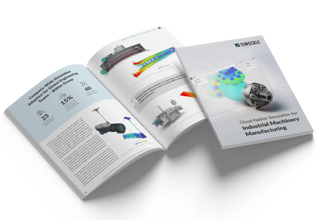
Cloud-Native Simulation for Industrial Machinery Manufacturing
Our latest eBook explores how cloud-native simulation is transforming the challenges of industrial machinery manufacturing (including valves) into opportunities. Download it for free by clicking the button below.
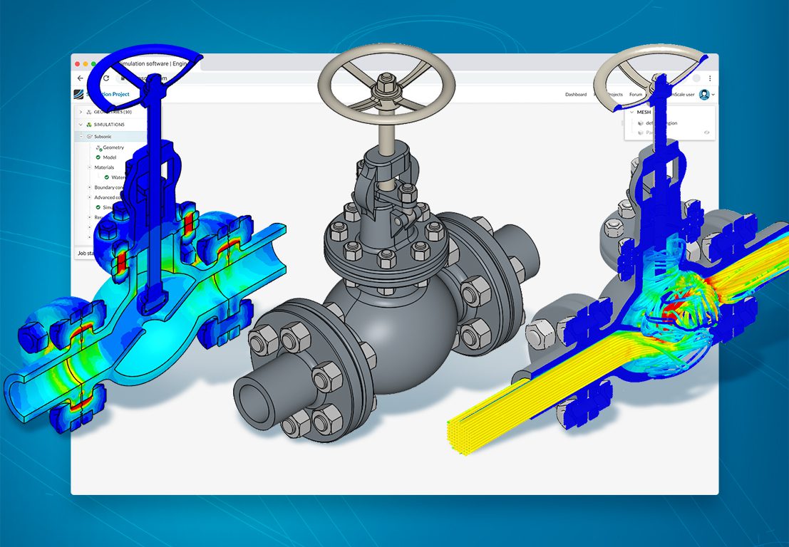
Valve CFD Analysis with SimScale
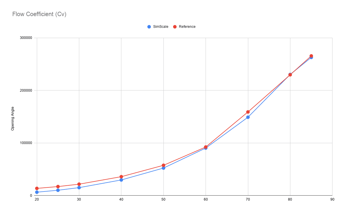
SimScale’s platform offers robust capabilities for simulating the performance of various valves. For instance, it can optimize internal flow through valves, significantly enhancing the volume of fluid that can pass through, particularly in scenarios where valve size is a constraint. It also facilitates the reduction of pressure drop by identifying and addressing non-ideal flow paths that cause separation and blockages. It can help avoid water hammer and identify and mitigate flow regions with high cavitation risks. Moreover, it allows for the prediction of \(C_v\) by plotting the valve flow coefficient curve, which is crucial for selecting the right valve sizing for specific applications [2].
Globe Valve Simulation in SimScale
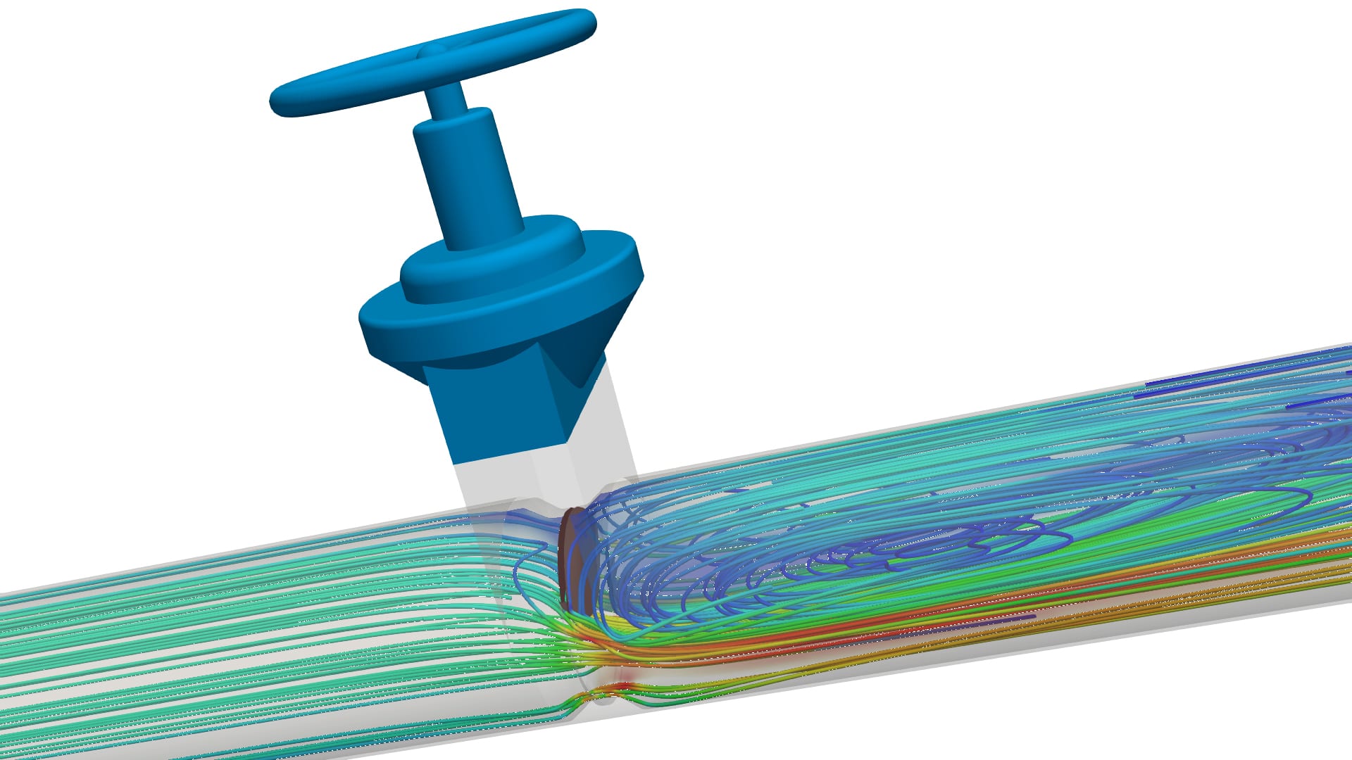
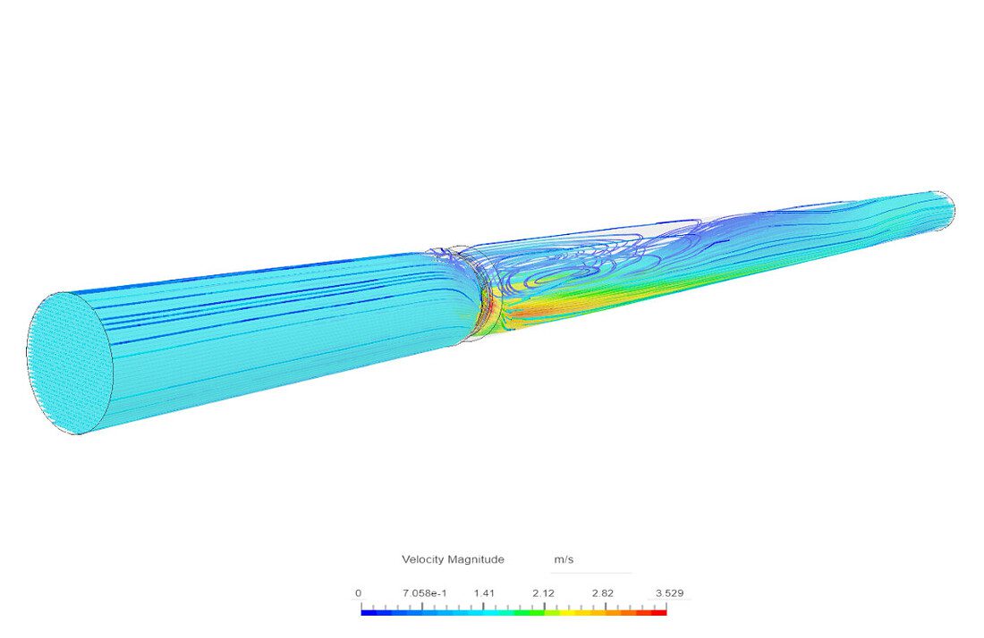
Globe valves are primarily utilized for regulating fluid flow in pipelines. Thus, simulating them accurately and efficiently is essential to ensuring high performance. A project featured on SimScale showcases how simulation can help in evaluating the flow coefficient of globe valves.
This study focuses on calculating the flow coefficient (Kv) of a globe valve with an internal diameter of 40 \(mm\), using incompressible steady-state flow analysis with K-Omega SST turbulence for water flow. The project simulation involved a pressure drop of 1 bar across the valve with an inlet pressure of 100,000 \(Pa\), an outlet pressure of 0 \(Pa\), and a no-slip velocity wall condition.
After 1000 iterations ran in less than 42 minutes, the resulting valve flow coefficient was found to be 25.8. This showcases the valve’s performance under specified conditions, highlighting the relationship between pressure loss and fluid velocity, which aligns with theoretical expectations.
Gate Valve Simulation in SimScale
Gate valves, functioning by raising a barrier to control fluid flow, are distinct in requiring minimal space along a pipe’s axis and providing low resistance to fluid flow when fully open. SimScale’s platform is ideal for iterative design testing of these gate valves.
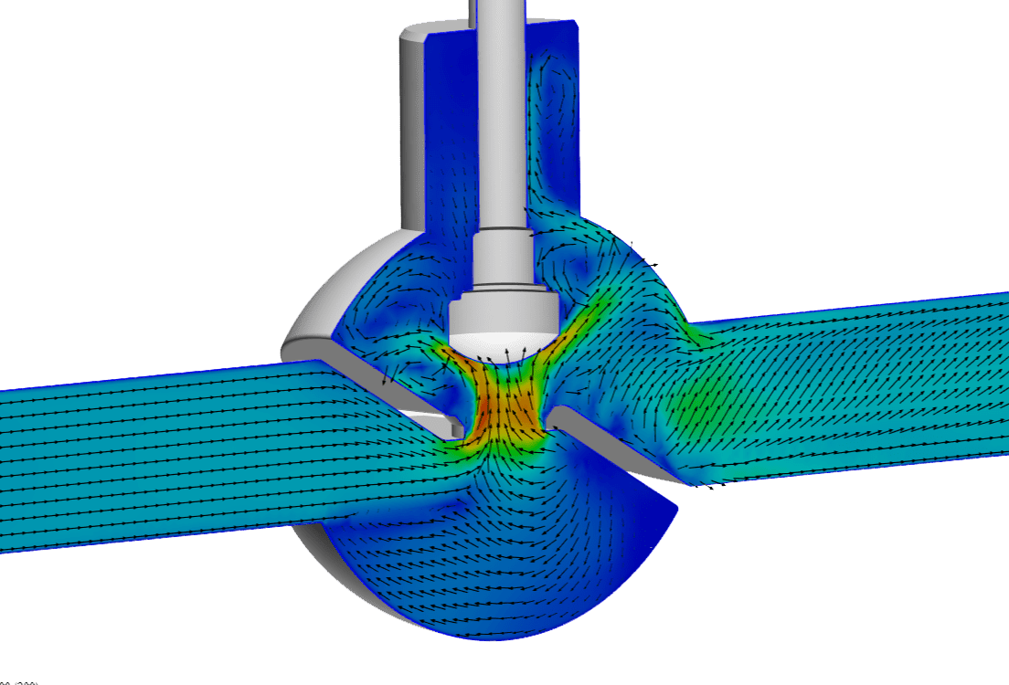
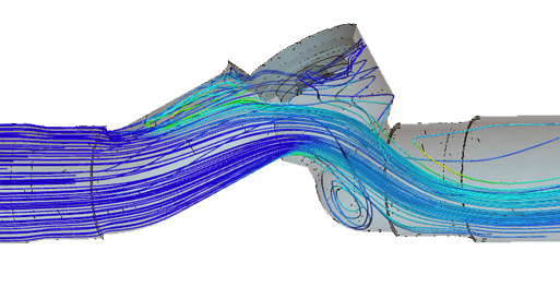
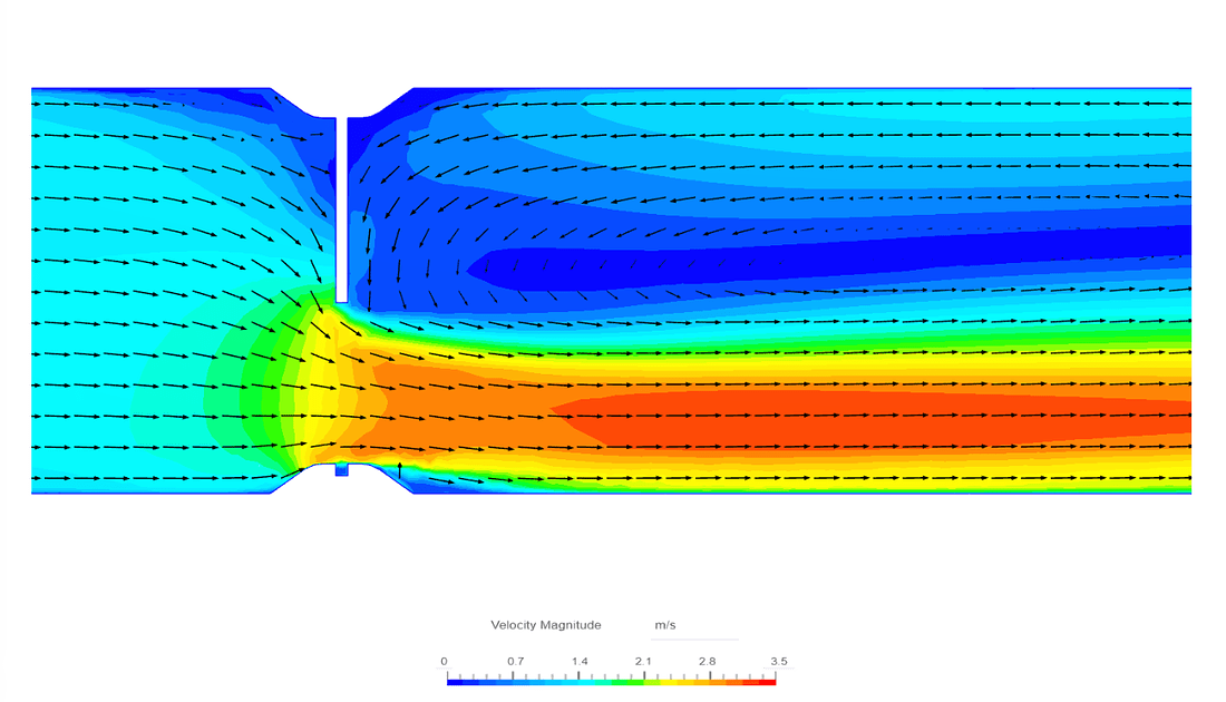
In this SimScale project on water flow analysis through a gate valve, the performance of a half-open gate valve in a cylindrical pipe (D = 68 \(mm\)) was simulated. The valve, integral in controlling water flow, was examined under steady-state turbulent flow conditions with a velocity inlet of 1 m/s and an outlet pressure of 0 \(Pa\). The simulation, utilizing a mesh of 1.1 million cells, focused on the dynamics of water flow, particularly observing recirculation zones and pressure drops post-valve. This was simulated using the K-Omega SST model.
Results highlighted a spike in velocity after the valve, conforming to the principle of continuity, and pressure contours indicated a drop in pressure due to increased velocity and obstruction by the half-open valve. This analysis provides insights into the fluid dynamics at play in a gate valve.
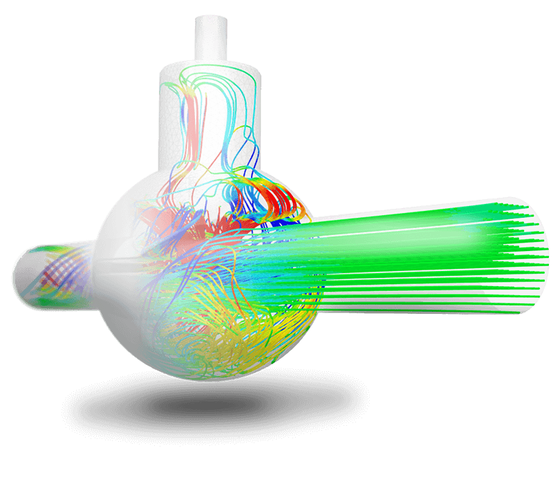
Ball Valve Simulation in SimScale
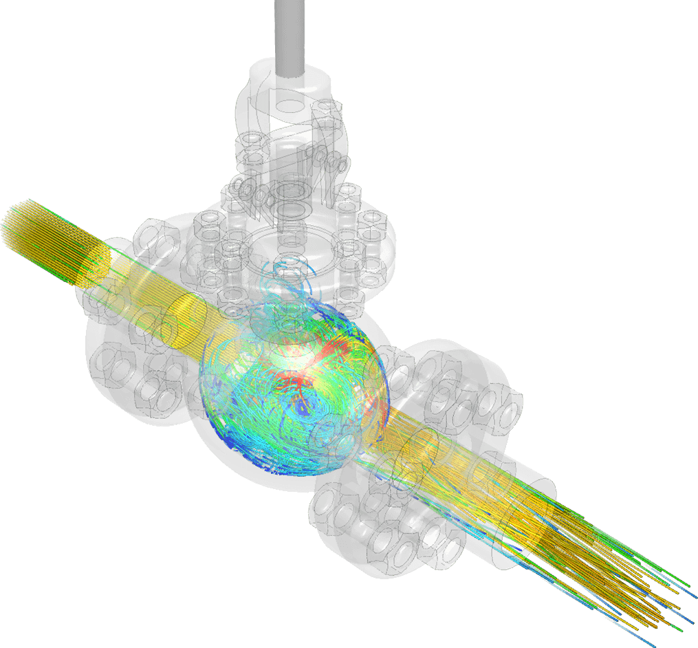
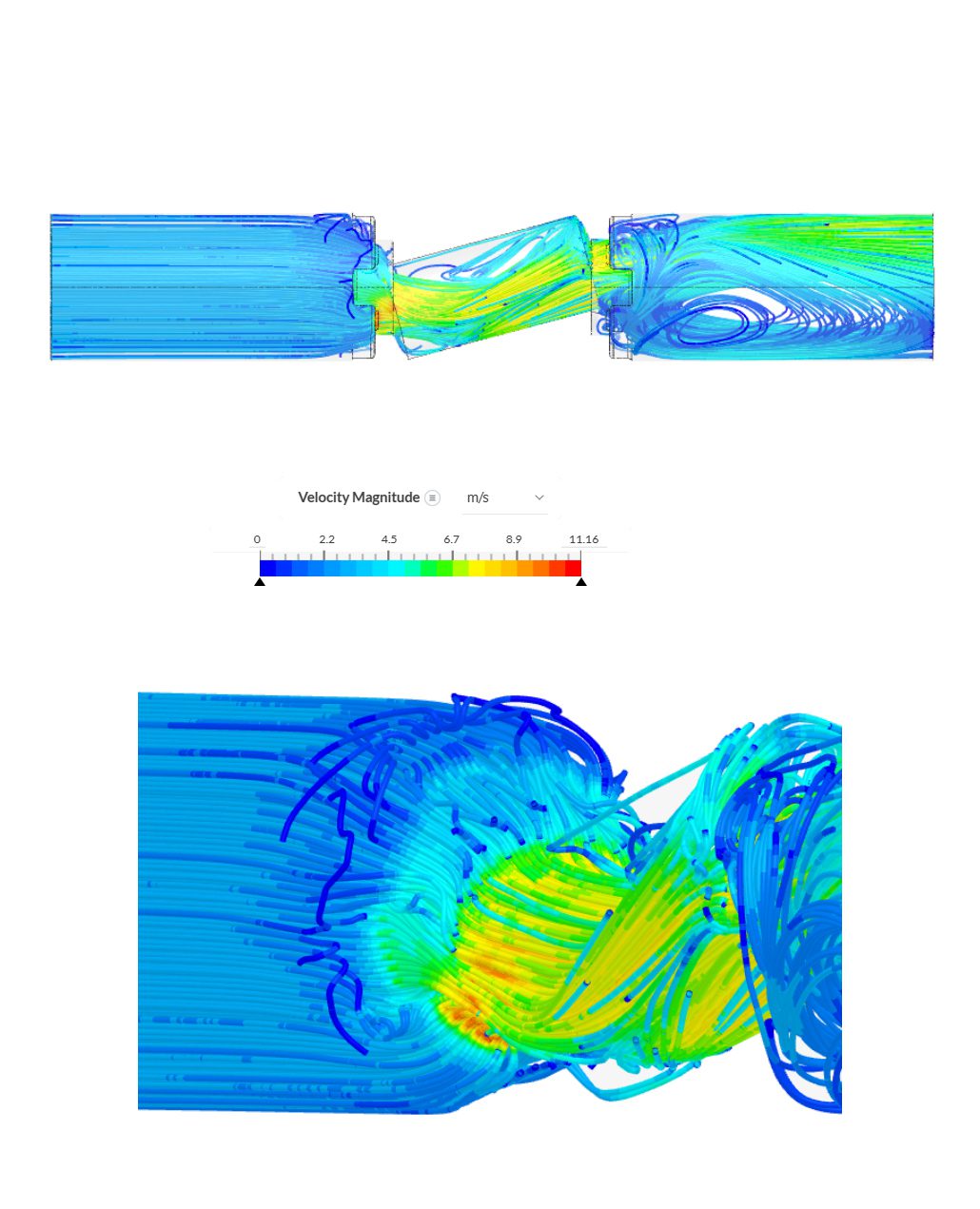
Ball valves are crucial in various scenarios, including flow and pressure control for different fluids and gases, and in industries like oil and natural gas or chemical storage. SimScale facilitates the early design analysis of these valves, optimizing pressure drop and force behavior. A project in SimScale investigated the behavior of water flow through a ball valve. The study focused on a full port, cavity-filled ball valve design. The simulation used a Standard mesh with 1 million cells and the K-Omega SST turbulence model for incompressible flow analysis.
The results showed a significant pressure drop and recirculation within the hollow tube, due to the unique positioning of the tube, impacting the fluid flow and pressure dynamics. This analysis is vital for understanding the behavior of ball valves in real-world applications, especially in contexts where precise flow control is necessary.
Advantages of Using SimScale Valve CFD Simulation
SimScale’s cloud-native platform eliminates traditional challenges associated with valve simulation, such as the high cost of hardware and steep learning curves. The platform offers engineers and designers several advantages, including:
- Parallel Simulations: Engineers can run multiple simulations simultaneously, speeding up their design optimization process.
- User-Friendly Interface: The platform is easy to learn, making it accessible for a wider range of users.
- Maintenance-Free Operation: There is no need for manual updates, installations, or maintenance.
- Versatile Simulation Capabilities: SimScale supports various types of simulations, including CFD, FEA, thermal analysis, and electromagnetics.
Mastering the Flow Valve Coefficient Analysis with SimScale
In valve design and fluid dynamics, the valve flow coefficient is a vital parameter. SimScale’s cloud-native simulation platform is used for simulating fluid flow through valves and optimizing the valve flow coefficient across various valve types.
For those involved in fluid dynamics and valve engineering, embracing SimScale offers an opportunity to refine designs with precision and efficiency, ensuring optimal valve performance in a range of applications. If you’re seeking to elevate your valve design and analysis with cutting-edge simulation technology, simply sign up below and start simulating directly in your web browser.
References
- Zhou, X.-M., Wang, Z.-K., & Zhang, Y.-F. (2017). A simple method for high-precision evaluation of valve flow coefficient by computational fluid dynamics simulation. Advances in Mechanical Engineering, 9(6).
- Gao, Z.-X., Yue, Y., Yang, J.-M., Li, J.-Y., Wu, H., & Jin, Z.-J. (2021). Numerical study of the microflow characteristics in a V-ball valve. Micromachines, 12(2), 155.
Last updated: January 8th, 2025
Did this article solve your issue?
How can we do better?
We appreciate and value your feedback.
What's Next
What Is FEA? Finite Element Analysis Explained

