What is Lift Coefficient?
Lift coefficient, usually denoted as \(C_L\), is an expression of the lift force generated on an object with respect to the density and velocity of the fluid flowing around it, as well as the surface area over which this lift acts. It is a dimensionless quantity and is very useful in aircraft design and manufacturing and in other fields as well. In this article, we will go into further detail about lift, why lift coefficient is important, and how these values can be manipulated for use in industry.
What is Lift Coefficient?
To answer the question of what lift coefficient is, we must first understand what lift is. Lift is the perpendicular component of the force exerted by a surrounding fluid on an object due to the relative motion between them. As the name implies, the lift force is usually in the upwards direction against the gravitational pull, but it can technically act in any direction perpendicular to the direction of fluid flow. The usual fluid of interest is air, but it could be a liquid medium (like water), as well. For the purposes of this article, we will restrict our focus to air as the default fluid.
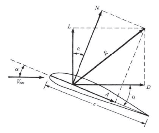
As shown in Figure 1, lift \(L\) is the component of the aerodynamic force \(R\) being exerted by the flowing fluid with velocity \(V_∞\) (also referred to as freestream velocity). The component of the force \(R\) that is parallel to the direction of the freestream velocity is known as drag \(D\). \(A\) is called the axial force, and it is the component of \(R\) parallel to the length of the body \(c\). Whereas \(N\), called the normal force, is the component of \(R\) perpendicular to \(c\).
Important Equations to Calculate Lift Coefficient
Lift coefficient \(C_L\) is expressed mathematically as:
$$ C_L = \frac{L}{qS} $$ or $$ C_L = \frac{2L}{\rho U^2 S} $$
Where:
\(L\) is the lift (or lift force),
\(S\) is the reference surface area of the object,
\(q\) is the dynamic pressure,
\(\rho\) is the fluid’s density,
\(U\) is the velocity of the fluid.
Lift coefficient is dimensionless as the dimensions in the equation cancel out. It is a property of an object and how it is shaped, which tells us how much lift can be generated from a certain velocity and density of a fluid. When an object is well manufactured to maximize its lift and minimize its drag, this object is referred to as an aerofoil, airfoil, wing, or blade [2].
A cross-section of an airfoil is often taken for study with nomenclature to define all the dimensions and properties of the shape, as shown in Figure 2.
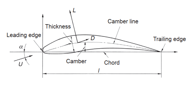
The chord is the straight line between the leading edge and the trailing edge of the airfoil, while the camber line is the curved line between these two points through the middle of the airfoil. The elevation of the highest point of the camber line from the chord is called the camber. The thickness of the airfoil is its maximum length when measured perpendicular to the camber line. The angle \(\alpha\) between the direction of fluid flow \(U\) and the chord is called the angle of attack.
Considering the width of the airfoil as \(b\) and its surface area as \(A\), the expression \(b^2/A\) is referred to as the aspect ratio. With the length of the chord \(l\), the area \(A\) of the airfoil can be expressed as \(b \times l\), and so the aspect ratio can be rewritten as \(b^2/A\) or \(b/l\).
The study of three-dimensional flow is often very complicated, and to simplify the theory, a two-dimensional section of the airfoil is usually adopted where the lift coefficient can be deconstructed into what is called the section lift coefficient, \(c_l\). The span of the airfoil is assumed to be infinite and, as such, no longer a variable. So, the equation replaces the surface area with the chord length to give \(c_l\) as:
$$ c_l = \frac{L}{ql} $$ or $$ c_l = \frac{2L}{\rho U^2 l} $$
Difference Between Lift Coefficient and Drag Coefficient
Lift coefficient and drag coefficient are essentially the same thing with one key distinction: they are coefficients measuring how much of the aerodynamic force constitutes lift and drag, respectively.
Drag coefficient \(C_D\) is expressed as:
$$ C_D = \frac{D}{qS} $$ or $$ C_D = \frac{2D}{\rho U^2 S} $$
Where \(D\) is the drag force, and the other parameters remain the same as above.
Similarly, section drag coefficient \(c_d\) is given as:
$$ c_d = \frac{D}{ql} $$ or $$ c_d = \frac{2D}{\rho U^2 l} $$
In addition to the lift and drag coefficients, there is another coefficient of interest called the moment coefficient. The lift and drag forces on a body act at an imaginary point called the center of pressure, which can be thought of in a similar sense as the center of gravity. This center of pressure varies along the airfoil as the angle of attack changes. To avoid this inconvenient variance in calculation, a fixed point is conventionally chosen on the airfoil, one-quarter of the chord length \(l\) from the leading edge, and this point is called the quarter chord. Moving the center of pressure to the quarter chord requires the moment at that point to be added to achieve force equilibrium.
Moment coefficient \(C_M\) is expressed as:
$$ C_M = \frac{M}{qSl_{1/4}} $$ or $$ C_M = \frac{2M}{\rho U^2 S l_{1/4}} $$
Where \(M\) is the moment, and \(l_{1/4}\) is the quarter chord.
Similarly, section moment coefficient \(c_m\) is given as:
$$ c_m = \frac{M}{ql_{1/4}^2} $$ or $$ c_m = \frac{2M}{\rho U^2 l_{1/4}^2} $$
Applications of Lift Coefficient
Having learned about lift coefficient, the natural question emerges: why is lift coefficient important? In the design and manufacture of aircraft, one of the critical aims is to increase, as much as possible, the lift component of the aerodynamic force against the drag component. Similarly, electric windmills, turbines, boat propellers, and helicopter propellers are manufactured with this information to maximize their efficiency. The lift coefficient is usually plotted against the angle of attack to give insight into the behavior of an airfoil section under certain fixed conditions to maximize lift and build more efficient machines, aircraft, or vehicles. These plots on a graph are referred to as the aerofoil characteristic curves, as shown in Figure 3 below.
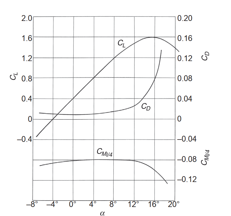
A few things are immediately apparent when this graph is examined. The lift coefficient is seen to rise steadily with increasing angle of attack, reaching a maximum, after which it starts to fall. At this point, the airfoil is said to experience stalling. The angle where the lift coefficient is at the maximum is called the stalling angle, and the angle where the lift coefficient is zero is called the zero-lift angle.
Figure 3 answers a common question: can the lift coefficient be greater than 1? In this example, it is seen to have a maximum value of 1.6, which is around the maximum for a fixed-wing. However, some designs, such as a rotating cylinder, can achieve lift coefficients of over 9 [3].
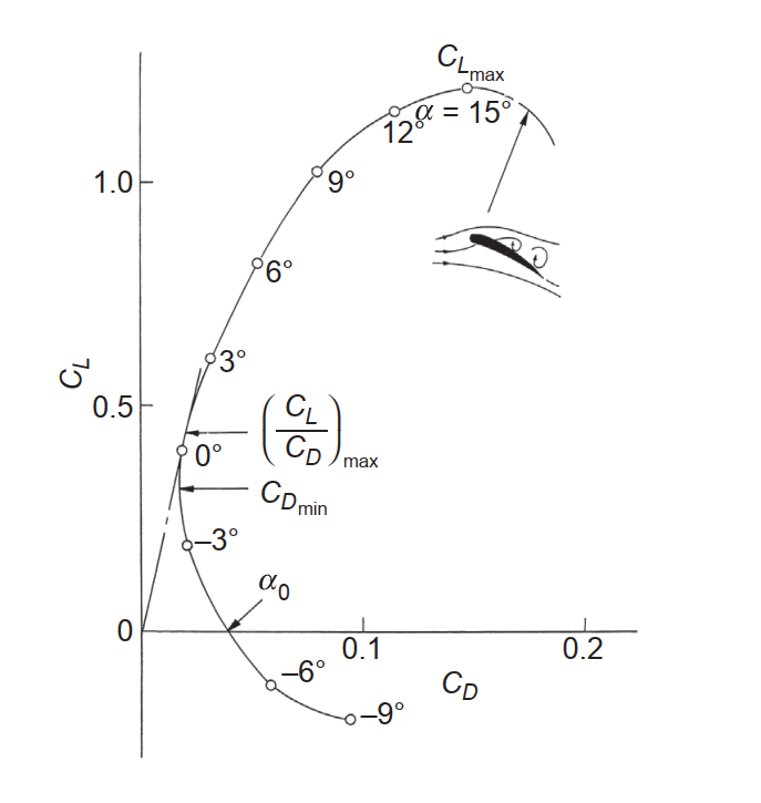
Lift and drag coefficients can also be plotted against each other, as shown in Figure 4, and from this, we can determine the angle of attack which would maximize the lift-drag ratio, denoted as (\(C_L/C_D)_{max}\).
Simulations Using Lift Coefficient
The values of lift, drag, and their respective coefficients are normally determined empirically in a wind tunnel using a scaled-down model of the body being tested. This is the case especially for very complex designs where a lot of factors need to be accounted for, and it is often easier to simply run physical tests. However, this would prove to be a very expensive undertaking if all the real-life conditions, such as air velocity, size of the body, etc., were to be met.
To make tweaks and changes to meet specific requirements, these tests can be carried out to a reasonable degree of accuracy via Computational Fluid Dynamics (CFD) simulations with some established base data. It is common to input these base data and vary others to study and analyze the behavior of airfoils and generate further aerodynamic data. This gives engineers the necessary information regarding the repeatability and reliability of their design over a wide range of conditions [4].
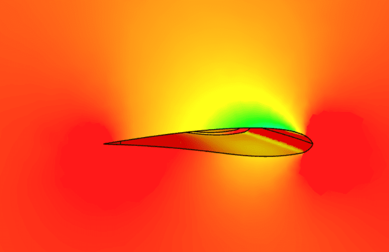
With its online CFD tool, SimScale enables engineers and designers to easily simulate aerodynamic cases early in the design process directly in their web browser without the hassle of hefty hardware and expensive prototyping. From studying the lift force on drones to investigating the compressible flow around a wing, SimScale CFD is a great tool for external aerodynamics and other CFD applications. Try it for yourself by clicking the “Start Simulating” button below.
References
- Anderson, John. “Fundamentals of Aerodynamics.” McGraw Hill (2017): 19 – 26.
- Nakayama, Yasuki. “Introduction to fluid mechanics.” Butterworth-Heinemann (2018): 177 – 200
- Burgers, Phillip, and David E. Alexander. “Normalized lift: An energy interpretation of the lift coefficient simplifies comparisons of the lifting ability of rotating and flapping surfaces.” Plos one 7.5 (2012): e36732.
- AeroToolbox, “Aerodynamic Lift, Drag and Moment Coefficients” https://aerotoolbox.com/lift-drag-moment-coefficient (accessed July 26, 2023)
Last updated: September 1st, 2023
Did this article solve your issue?
How can we do better?
We appreciate and value your feedback.
What's Next
What is Net Positive Suction Head (NPSH)?

