When you think of optimizing a design in an external aerodynamics simulation, the first thing you need to quantify is the drag of the body under test. For example, if you want to analyze an airplane or a car, we would mainly focus on the three dominant design parameters, such as lift and drag. This article describes how to analyze the pitch, lift, and drag coefficients using the example of an airplane.
Approach
This can be achieved in the SimScale Workbench by simply setting the result outputs as described below. Inside the simulation tree, go to Result control > Forces and moment coefficients.

A settings panel for Forces and moment coefficients will appear with parameters as shown in Figure1. The required parameters are discussed below:
Center of Rotation
The Center of rotation is commonly defined as the center of mass of the structure. In some simulation projects, it may be convenient to define different coordinates for the center of rotation while others can be tricky.
Lift and Drag Direction
You need to assign those according to your coordinate system. As the picture above demonstrates, drag pulls the aircraft back. In our example, drag is in the positive x-direction. This is why we need to set the value for Drag direction dx to 1. Accordingly, when looking at the Lift direction, dy is set to 1, and the Pitch axis automatically corresponds to the axis not being used; in this particular case, the z-axis is designated as the Pitch axis.
Freestream Velocity
Freestream velocity is the velocity of your airplane or vehicle in most cases. For simulation purposes, you can choose the inlet velocity here.
Reference Length and Area
We need the Reference length, to analyze the pitch coefficient. It is important to take the same value for all your calculations in order to be able to compare them. For this example, it is the wingspan.
The Reference area is important for calculating the lift and drag coefficients. Depending on the industry and the application, different areas are commonly used. One possibility is to use the frontal area which is often used as the reference area for calculating the drag coefficient. However, one can also use the wing area as the reference area, which is often used if one is rather interested in the lift coefficient. Make sure to use the same value for all your calculations.
Note
Note that both reference length and area can change for specific cases, so we recommend finding it out for your specific application.
Assigned Faces
Pick the faces for which you want to analyze the coefficients. You can do this for specific parts such as wings or tail only or the whole assembly.
Computation of the Coefficients
On the simulation results you will find a plot of the following quantities as a function of time (or iteration count, depending on the setup), similar to this one:
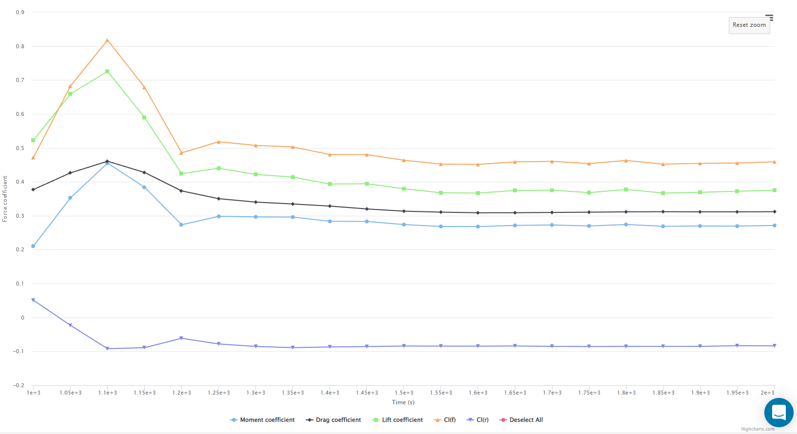
It includes curves for the following quantities:
- Lift coefficient: normalization of the lift force, with respect to a reference force equal to the dynamic pressure times the reference area value. Computed as follows:
$$ Cl = \frac{ \vec{F}_{tot} \cdot \vec{l} }{ A_{ref}\ p_{Dyn} }$$
- Drag coefficient: normalization of the drag force to the reference force.
$$ Cd = \frac{ \vec{F}_{tot} \cdot \vec{d} }{ A_{ref}\ p_{Dyn} } $$
- Moment coefficient: normalization of the total moment around the pitch axis, with respect to the reference force times the reference length.
$$ Cm = \frac{ \vec{M}_{tot} \cdot \vec{p} }{ A_{ref}\ L_{ref}\ p_{Dyn} } $$
- Front lift coefficient: (normalized) lift acting on the front half of the object.
$$ Cl(f) = \frac{ Cl }{ 2 } + Cm $$
- Rear lift coefficient: (normalized) lift acting on the rear half of the object.
$$ Cl(r) = \frac{ Cl }{ 2 } – Cm $$
Where:
- \( \vec{F}_{tot} \) is the total force vector
- \( \vec{M}_{tot} \) is the total moment vector
- \( \vec{l} \) is the lift direction vector
- \( \vec{d} \) is the drag direction vector
- \( \vec{p} \) is the pitch direction vector
- \( A_{ref} \) is the reference area value
- \( L_{ref} \) is the reference length value
- \( p_{Dyn} = \frac{1}{2} \rho | U_{\infty} |^2 \) is the dynamic pressure
- \( \rho \) is the fluid density
- \( U_{\infty} \) is the freestream velocity
In ground vehicle aerodynamics, the front lift coefficient Cl(f) and the rear lift coefficient Cl(r) can be used to obtain the downforces acting on the front and rear axles, respectively:
$$ F_F = Cl(f) F_{REF} = Cl(f) A_{REF} p_{Dyn} $$
$$ F_R = Cl(r) F_{REF} = Cl(r) A_{REF} p_{Dyn} $$
Note
If none of the above suggestions solved your problem, please post the issue on our forum or contact us.


