What is Bending Stress?
Bending stress is a pivotal concept in solid mechanics and structural analysis. Every structure, from towering skyscrapers to the smallest mechanical components, consists of various parts that contribute to the structure’s ability to bear loads and resist deformation.
In this context, bending stress stands out as a crucial aspect, especially in scenarios where elements like beams bend under load. For that reason, a thorough understanding of the mechanics of materials and how different materials react under stress is essential, particularly in terms of the impact of bending stress and the associated normal stress on a structure.
In this article, we describe what bending stress is, how it is calculated, and how it applies to particular cases like beam bending. We also discuss the role of simulation analysis in visualizing and gaining better insights into bending stress in various contexts.
Definition of Bending Stress
Bending stress is the internal resistance generated within a component when an external bending moment or force is applied. This bending moment induces curvature in the component, leading to the development of tension and compression stresses, collectively known as bending stresses.
The theory behind bending stress involves two critical assumptions – the plane section assumption and the linear elastic material behavior.
- The plane section assumption suggests that any cross-section of a structure remains plane after bending.
- The linear elastic material behavior presupposes that the normal stress is directly proportional to the strain, a relationship known as Hooke’s Law.
For instance, the bending stress in a beam is not uniformly distributed across its cross-section. The maximum stress occurs at the outermost layers of the beam – the ones furthest from the neutral axis, a line along the length of the beam where the bending stress is zero.
Understanding bending stress plays a significant role in determining the overall strength and longevity of structures. Excessive bending stress can lead to deformation, failure, or even the collapse of structures. Therefore, it’s essential for designers and engineers to comprehend the theoretical underpinnings of bending stress and normal stress to predict and prevent structural failure.
Studying the mechanics of materials, which involves how different materials respond to various types of stress, provides a crucial foundation for understanding bending stress. This knowledge assists in the selection of appropriate materials and designs that can effectively withstand bending stresses, ensuring structural safety and reliability.
How to Calculate Bending Stress: The Essential Formulas
The calculation of bending stress is based on a fundamental bending stress formula, which encapsulates the applied moment, the distance from the neutral axis to the point of interest, and the moment of inertia of the cross-sectional area. The standard formula for calculating bending stress (\(\sigma\)) is1:
$$ \sigma = M \frac{\gamma}{I} $$
where:
\(M\) represents the moment or bending force applied to the component,
\(\gamma\) is the distance from the neutral axis to the point at which stress needs to be calculated, and
\(I\) is the moment of inertia of the cross-sectional area about the neutral axis.
The moment of inertia is calculated differently depending on the geometry of the cross-section. It indicates the resistance to bending provided by a particular shape. For a rectangular cross-section, the moment of inertia (\(I\)) can be determined using the formula2:
$$ I = \frac{b \cdot h^3}{12} $$
where:
\(b\) is the breadth of the rectangular section, and
\(h\) is the height of the rectangular section.
By adjusting the value of ‘\(\gamma\)’ from the neutral axis to the top or bottom of the cross-section, you can understand the variation in bending stress across the cross-section of a beam. These are the locations where the maximum bending stress occurs.
Accurately calculating bending stress is essential in structural analysis. It helps determine if the chosen material and design can withstand the imposed loads without yielding or failing. If the calculated bending stress exceeds the allowable stress of the material, a design modification or material substitution may be required to ensure the structural safety and reliability of the component under consideration.
The Science of Beam Bending
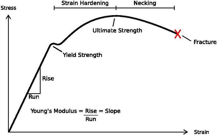
A fundamental principle within the mechanics of materials is the relationship between stress and strain, defined by the modern theory of elasticity, which is a generalization of Hooke’s Law. It states that stress applied to a material is directly proportional to the strain it produces, provided the material has not reached its yield strength. Mathematically, this relationship is represented by the following equation [2]:
$$ \sigma = E \cdot \epsilon $$
where \(\sigma\) is the stress, \(E\) is the modulus of elasticity (or Young’s Modulus), and \(\epsilon\) is the strain.
This can be further visualized in a stress-strain curve, which demonstrates how a material behaves under load, giving insights into the material’s strength, stiffness, ductility, and failure limits. When a material is subjected to stress, it undergoes strain and potentially shape change. This behavior can be graphically represented on a stress-strain curve. The curve typically starts with a linear region, where Hooke’s Law applies. Beyond the elastic limit (also referred to as yield strength), the material will deform plastically and may eventually fail if the stress continues to increase.
Beam bending is arguably one of the most common examples of bending stress analysis. A beam is a generic object with a constant cross-section along its length. Its length is significantly larger than the dimensions of its cross-section, allowing for relatively precise approximations. Given its simplicity, a beam is a good approximation for other structures, which can be viewed as one beam or a group of beams.
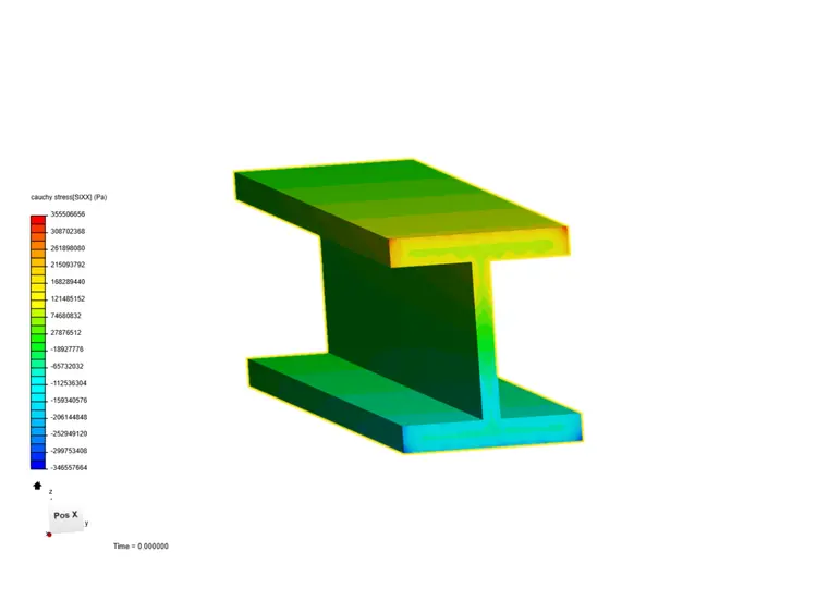
Bending a beam, like any other structure, would mechanically deform it, either elastically or plastically, depending on the material’s yield strength and the stress magnitude. Here’s an example of stress analysis in a beam. Using FEA static analysis in SimScale (explained in the following section), the designer analyzed the bending stress, axial tension, and compression in the flanges.
Simulation Analysis: Analyzing Bending Stress Using FEA
Simulation analysis has revolutionized how engineers approach structural analysis. It provides a platform to accurately predict and analyze how structures respond to various forms of stress, including bending stress. This powerful tool empowers engineers and designers to foresee the performance of their designs under different loading conditions and optimize them before they are manufactured.
Finite Element Analysis (FEA), a subset of simulation analysis, is instrumental in this context. FEA is a numerical method used to predict how a part or assembly behaves under given conditions. It involves creating a mesh made of numerous small, simple ‘finite elements,’ such as tetrahedra or cubes. These elements are interconnected at ‘nodes,’ and the entire mesh can be used to create a close approximation of the original structure. The behavior of each finite element under load is calculated using the relevant equations, such as the bending stress formula for bending cases, and these results are aggregated to provide an overall picture of how the structure would react under the specified loading conditions.
FEA enables engineers to visualize areas of high bending stress (and other types of stress) within a design, thereby identifying potential points of weakness or failure. By conducting such an analysis during the design stage, it’s possible to implement design modifications that improve the structure’s ability to withstand bending stress, enhancing safety and efficiency while reducing material waste and cost.
In addition, simulation analysis allows for considering various factors that might be impractical to test physically, such as extreme loading conditions or the impacts of long-term use. It also allows comparative studies between different design configurations, materials, or load conditions to optimize the structure’s performance.
In bending stress analysis, simulation empowers a more in-depth understanding, complementing theoretical knowledge with practical insights. It facilitates the creation of safer, more efficient structures, allowing for design optimization and aiding in decision-making processes. This makes it an indispensable tool for today’s engineers and designers, underlining the value of simulation analysis as an integral part of the modern approach to analyzing bending stress.
Bending Analysis in SimScale
Simulating bending cases in SimScale gives you quick and accurate stress visualization to understand and measure the stress distribution on the part. Using the static simulation module in SimScale, you can run a non-linear FEA analysis, which allows you to take into account phenomena such as:
- Non-elastic materials (plasticity in this case)
- Varying loads
- Large displacements and rotations
It incorporates the ability to define non-linear material behavior beyond the yield point. It enables you to test and predict the behavior of structures virtually and, therefore, solve complex structural engineering problems under various static loading conditions.
SimScale’s FEA simulation platform uses scalable numerical methods that can calculate mathematical expressions for structural analysis that would otherwise be very challenging due to complex loading, geometries, or material properties.
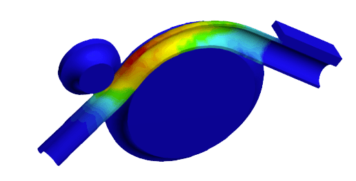
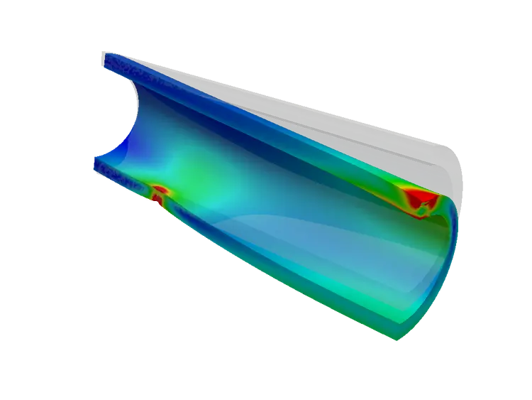
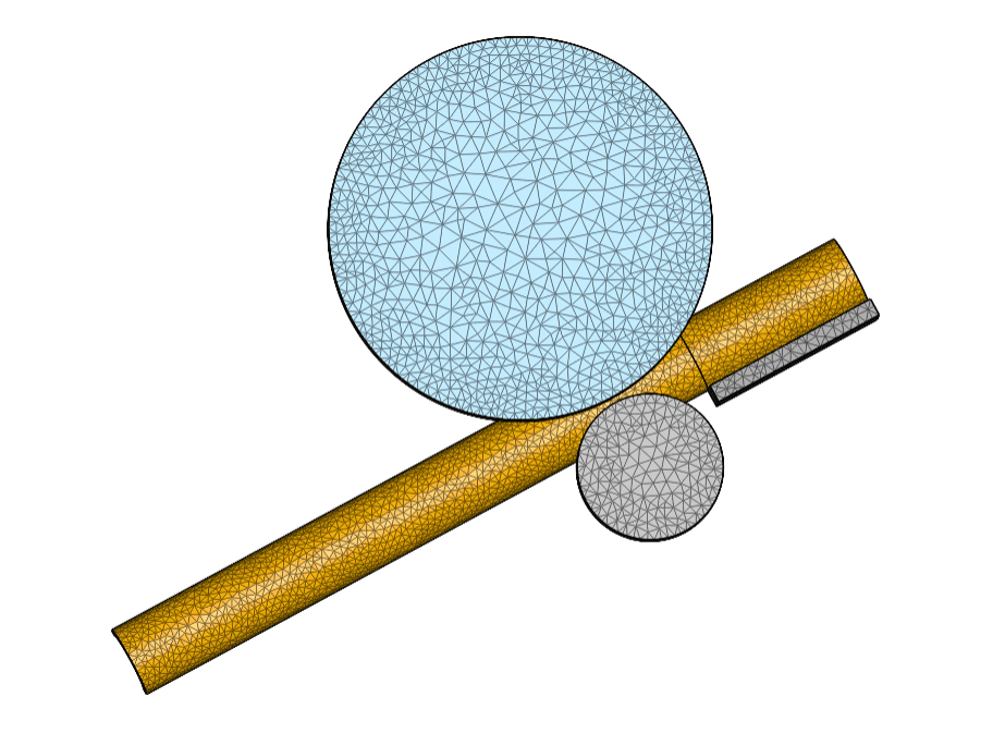
For instance, here is a step-by-step tutorial for how you can simulate the bending of an aluminum pipe using nonlinear static simulation. This tutorial describes how you can analyze the deformation and stress distribution developed on the pipe during the bending process, including nonlinear phenomena such as material plasticity, physical contact, and large deformation.

Conclusion: Importance of Bending Stress Simulation
Understanding bending stress, which involves delving into the mechanics of materials and the application of specific formulas, is essential in structural analysis for both safety and efficiency. With technological advancements, simulation analysis has risen as an indispensable tool, providing engineers with predictive insights and allowing for improved designs before their physical realization.
In structural engineering, mastering bending stress through both theoretical comprehension and simulation analysis is foundational. In essence, understanding bending stress equips designers and engineers to determine not just whether a structure can bear the load but how well it can do so. This understanding, paired with the utilization of a simulation tool like SimScale, helps to ensure safer, more efficient designs.
References
- Beer, F. P., Johnston, E. R., DeWolf, J. T., & Mazurek, D. F. (2020). Mechanics of Materials (8th ed.). New York: McGraw-Hill.
- Hibbeler, R. C. (2022). Mechanics of Materials (11th ed.). Pearson.
Last updated: January 16th, 2024
Did this article solve your issue?
How can we do better?
We appreciate and value your feedback.
What's Next
Principal Stress and Principal Strain: An Overview

