Principal Stress and Principal Strain: An Overview
Principal stress and principal strain are fundamental concepts in structural engineering and design, underpinning the evaluation and analysis of materials and structures. Integral to the safety and stability of various applications, these terms reflect the internal forces and deformations that materials undergo when subjected to external loads. The significance of understanding these concepts is echoed in the applications of the principal stress formula and principal strain equation, tools that allow professionals to assess and mitigate potential risks in design.
In this overview, we will explore the essence of these terms, their mathematical formulations, and their implications in real-world scenarios. We will also discuss related concepts like Mohr’s circle and draw a distinction between von Mises stress and principal stress. By understanding these core principles, professionals can ensure the structural integrity of their designs, from civil infrastructure to advanced aerospace components.
What is Principal Stress?
Principal stress represents the maximum and minimum normal stresses that occur within a material when subjected to complex loading conditions. It is essential to understand this concept as it provides insights into the material’s response and its potential points of weakness. When materials are subjected to multi-directional stresses, determining the principal stress can reveal the most severe stress concentrations, which are critical to avoiding structural failures.
The principal stress formula for the maximum (\(\sigma_1\)) and minimum stresses (\(\sigma_2\)) is given by [1]:
$$ \sigma_1 = \frac{(\sigma_x + \sigma_y)}{2} + \sqrt{\left(\frac{\sigma_x – \sigma_y}{2} \right)^2 + (\tau_{xy})^2} $$
$$ \sigma_2 = \frac{(\sigma_x + \sigma_y)}{2} – \sqrt{\left(\frac{\sigma_x – \sigma_y}{2} \right)^2 + (\tau_{xy})^2} $$
Where (\(\sigma_x\)) and (\(\sigma_y\)) are the normal stresses in the x and y directions, and
\(\tau_{xy}\) is the shear stress.
The importance of principal stress can’t be understated, especially when we delve into its calculation using the principal stress formula. This formula, rooted in equilibrium and material mechanics, gives an accurate representation of the stress experienced by the material. The principal stress equation ensures that designs are not only optimal but also safe.
But what is the ultimate stress a material can undergo? This leads us to the concept of maximum principal stress. Recognizing this value is pivotal for failure analysis, as it designates the highest level of stress the material is subjected to. In structural engineering and design, understanding the maximum principal stress can be the difference between a durable, long-lasting structure and an impending failure.
Cauchy Stress Tensor
The Cauchy Stress Tensor, often simply referred to as the stress tensor, is a foundational concept closely linked with principal stress. It provides a comprehensive representation of the stress state within a material element. Essentially, the stress tensor describes both the magnitude and direction of the normal and shear stresses acting on all possible orientations of a plane within a deformable body.
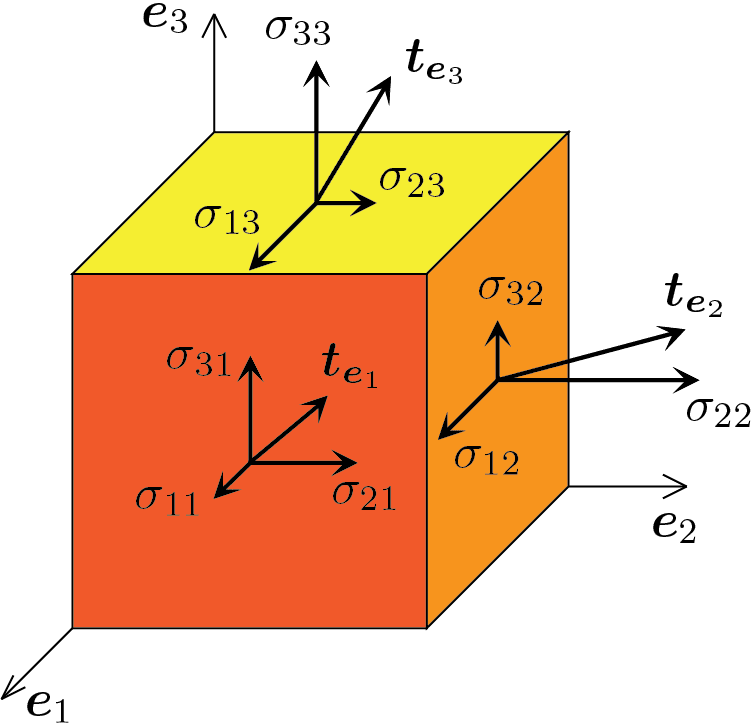
Understanding the stress tensor is crucial, as it forms the basis for further deriving the principal stresses. By diagonalizing the stress tensor, we can determine these principal values, which highlight the most and least stressed states within the material. Such a transformation process is pivotal, especially when examining complex stress scenarios, as it helps pinpoint the true nature and direction of the maximum stresses.
In the realm of structural analysis, harnessing the information from the Cauchy Stress Tensor and its relationship to principal stress ensures that engineers can make informed decisions about material safety, performance, and design modifications.
Mohr’s Circle
A commonly used graphical representation of stress analysis is Mohr’s Circle, an essential tool for engineers. This 2-dimensional graphical method enables a clear visual interpretation of stress transformation, essentially shedding light on the relationship between normal and shear stresses in materials.

Mohr’s Circle isn’t just a visualization technique—it’s a bridge to understanding the core concepts of principal stress. By plotting the normal and shear stresses on the circle, it becomes straightforward to identify the maximum principal stress and its corresponding orientation. The circle’s radius also provides insights into the magnitude of the resultant stresses.
The transformative power of Mohr’s Circle extends further, as it can also be employed for strain analysis, making it relevant for principal strain calculations. Understanding and correctly interpreting this graphical representation is key, especially when determining stress states that are most critical to the safety and functionality of a design.
As the field of structural engineering continues to evolve, Mohr’s Circle remains a steadfast tool, linking age-old principles with modern analytical techniques.
Principal Stress vs Von Mises Stress
The realm of structural analysis offers various criteria for understanding and predicting failure, two of which are principal stress and Von Mises stress. Though both aim to provide insights into material behavior under loading, they serve different purposes and are based on separate theories.
Principal stress can be seen as the maximum and minimum normal stresses acting on an element, providing vital data on the primary tensile and compressive stresses a material experiences. This becomes particularly crucial when analyzing brittle materials, as these stresses indicate potential fracture points.
On the other hand, Von Mises stress, also known as the equivalent or distortion energy stress, focuses more on the energy leading to yielding, especially in ductile materials. It’s a derived value aiming to predict the onset of yield and does not represent an actual stress component within the material.
When comparing principal stress and Von Mises stress, it’s crucial to recognize their individual strengths. For brittle materials, principal stress criteria often take the forefront, while Von Mises is the go-to for ductile materials. For a deeper understanding and a comprehensive comparison, readers can explore this detailed article on Von Mises stress.
What is Principal Strain?
Principal strain represents the maximum and minimum values of strain experienced in a material subjected to loading. Understanding strain is crucial as it offers insights into material deformation – how much a material stretches or compresses under applied stresses.
Strain, in general, is defined as the change in dimension divided by the original dimension. Mathematically, normal strain (\(\varepsilon\)) can be represented as [4]:
$$ \varepsilon = \frac{\Delta L}{L_0} $$
Where \(\varepsilon\) is the linear or normal strain,
\(\Delta L\) is the change in length of the material or object, and
\(L_0\) is the original or initial length of the material or object.
The concept of maximum principal strain is pivotal in design considerations, especially when evaluating how materials might behave under extreme loading conditions. This strain value provides engineers with data about the maximum stretching or compression a material undergoes, often serving as an indicator of potential material failure.
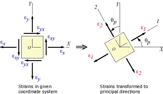
For those diving deeper into the topic, it’s beneficial to understand the principal strain formula and equation. Like principal stress, these strains occur on planes where the shear strain is zero. The equations to determine principal strains can be intricate, relying on the state of strain at a point in the material2:
$$ \varepsilon_1 = \frac{(\varepsilon_x + \varepsilon_y)}{2} + \sqrt{\left(\frac{\varepsilon_x – \varepsilon_y}{2} \right)^2 + \left(\frac{\gamma_{xy}}{2} \right)^2} $$
$$ \varepsilon_2 = \frac{(\varepsilon_x + \varepsilon_y)}{2} – \sqrt{\left(\frac{\varepsilon_x – \varepsilon_y}{2} \right)^2 + \left(\frac{\gamma_{xy}}{2} \right)^2} $$
Where \(\varepsilon_1\) and \(\varepsilon_2\) are the maximum and minimum principal strains, respectively.
\(\varepsilon_x\) and \(\varepsilon_y\) are the normal strains in the x and y directions, and
\(\gamma_{xy}\) is the engineering shear strain. Note that in some cases, this shear strain may be represented as half the value used in the principal strain equation, so it’s crucial to use the right definition.
Recognizing and calculating the maximum principal strain is essential for ensuring material and structural safety, providing a gauge to anticipate and prevent potential failures.
Applications in Engineering
In the world of engineering, understanding principal stress and principal strain is not just a theoretical need; it’s a practical necessity. These concepts play a central role in how structures are designed, analyzed, and optimized. Particularly in the field of structural engineering and design, calculating these principal values not only indicates the safety margins but also provides a deeper understanding of potential design optimizations.
Take civil engineering, for instance. When constructing bridges or skyscrapers, there’s a constant balance to strike between the weight of the structure, the forces acting on it, and the materials used. By referring to values like the maximum principal stress, engineers can predict where failures might occur and then design accordingly to avoid them.
For aerospace engineers, the stakes are incredibly high. Aircraft components face different stresses, from the forces of takeoff and landing to the pressures at high altitudes. Using the principal strain formula, they can assess how aircraft parts will deform or change shape under these conditions, ensuring safety in the skies.

And it’s not just about big structures and airplanes. In the automotive industry, cars are being made lighter and more fuel-efficient. Yet, they must remain safe. Engineers often use the principal stress equation to test and design car components, ensuring they can handle the stresses of the road while still being economical and efficient.

Overall, across various engineering disciplines, the applications of principal stress and strain are vast and critical. They guide decisions, ensuring both safety and performance in the final designs.
Simulation in Modern Analysis
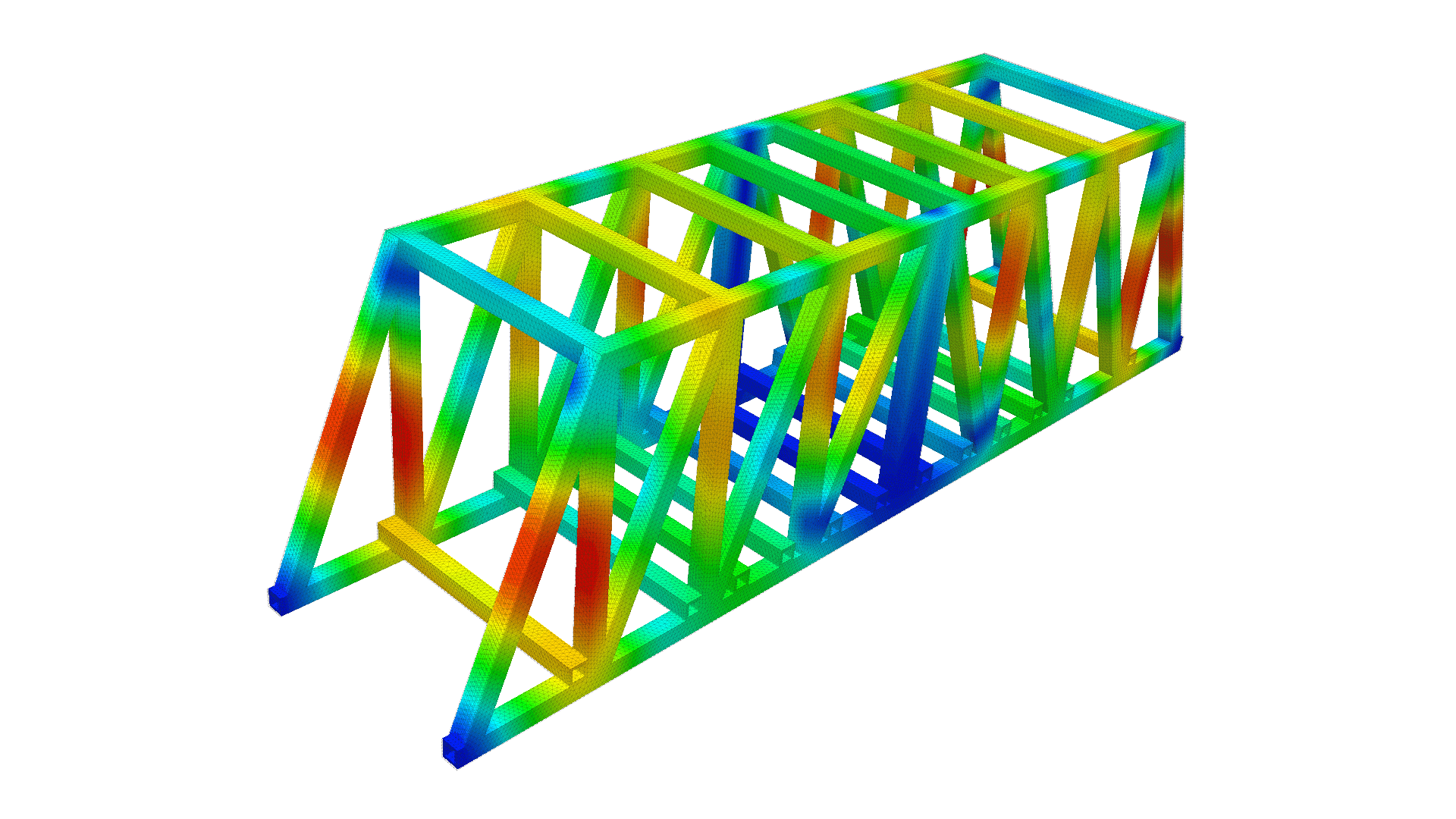
In today’s digital age, the power of computer simulations is revolutionizing the way we approach engineering challenges. Analyzing principal stress and principal strain has become more accurate, efficient, and detailed with modern computational tools.
Before the advent of these tools, engineers had to rely on hand calculations and small-scale physical tests. Now, simulations allow for a comprehensive view of how structures will respond to various forces, even before they are built. With software platforms, engineers can virtually apply loads, analyze stress distributions, and predict potential points of failure.
A prominent example of such a platform is SimScale. The SimScale FEA (Finite Element Analysis) capabilities provide a dynamic environment to evaluate principal stresses and strains in intricate structures. By using this tool, engineers can assess scenarios that might be too expensive, time-consuming, or even impossible to test physically.

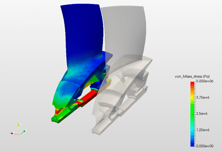
One crucial advantage of simulation tools is their ability to provide insights into the maximum principal stress and strain within complex geometries and under multifaceted loading conditions. This kind of deep analysis empowers engineers to optimize their designs, making structures safer and more efficient.
Furthermore, the discussion about von Mises stress vs principal stress gets enriched when visualized on simulation platforms. With clear visual representations, engineers can compare different stress values and make informed decisions about material selection, design modifications, and safety factors.
In essence, the convergence of simulation technology and the principles of principal stress and strain is shaping the future of engineering analysis. It not only saves time and resources but also pushes the boundaries of what’s possible in design and innovation.
References
- Bilotta, A., “Cauchy stress tensor tensor”, A first course on solid mechanics, Available at: https://antoniobilotta-structuralengineer.github.io/MyWebSite/SMbook_en/stress_sec_stress_chap_en.html
- Beer, F. P., Johnston, E. R., DeWolf, J. T., & Mazurek, D. F. (2020). Mechanics of Materials (8th ed.). New York: McGraw-Hill.
- https://blog.prepineer.com/how-to-construct-a-mohrs-circle/
- Timoshenko, S.P., & Goodier, J.N. (1982). Theory of Elasticity (3rd ed.). New York: McGraw-Hill.
- efunda, Calculators: Principal Strain, Available at: https://www.efunda.com/formulae/solid_mechanics/mat_mechanics/calc_principal_strain.cfm
Last updated: September 13th, 2023
Did this article solve your issue?
How can we do better?
We appreciate and value your feedback.
What's Next
What is Vibration Analysis?

