A well-designed cleanroom environment is necessary for activities performed in a controlled environment, containing a low level of pollutants—a critical requirement for many manufacturing, pharmaceutical, and scientific research applications. It has a controlled level of contamination, which is measured by the number of particles per cubic meter at a specified particle size. The ambient air outside in a typical urban environment contains 35,000,000 particles per cubic meter in the size range 0.5 µm or larger in diameter, which according to standards, is an ISO 9 cleanroom.
An ISO 1 room only allows 12 particles per cubic meter of diameter 0.3 μm or smaller [1]. It is absolutely necessary to maintain a high level of cleanliness in order to obtain the desired outputs from equipment and processes that are sensitive to environmental conditions.
The crucial decisions made during the design of a cleanroom environment affect the construction costs and also affect its operation in the long run. There are several configurations available to get the desired airflow and recirculation patterns in order to remove internally generated contaminants. The International Society for Pharmaceutical Engineering prescribes a training course on current Good Manufacturing Practice (cGMP), where one of the important course modules is HVAC solutions.
The training course focuses on the understanding of contamination control, the properties of air and the HVAC principles in critical environments, such as that of a cleanroom [2]. The American Society of Heating Refrigeration and Air-Conditioning Engineers (ASHRAE), also conducts courses on cleanroom design to highlight key topics such as airflow management, room layout, etc.[3]
Hence, it is important to understand the role of HVAC principles in a cleanroom environment. One of the best ways to recognize this is by performing simulations. Simulation technology is a cost-effective and time-efficient tool which helps during the design.
Download this case study for free to learn how the SimScale CFD platform was used to investigate a ducting system and optimize its performance.

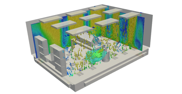
Cleanroom Ventilation Role of Engineering Simulation
How does engineering simulation help? Let’s consider the following 3 cases in which a possible contaminant leakage is assumed.
The cases have different ventilation configurations and we can compare them to find the best possible solution to eliminate the contaminant effect. In the simulation study, the flow is assumed to have a single pass, i.e., freshly treated air is allowed into the cleanroom environment every time.
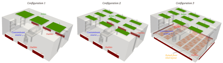
- Configuration 1 has central duct inlets and the exhaust along the floor.
- Configuration 2 has outlets similar to Configuration 1, but the inlet is distributed throughout the ceiling with multiple ducts.
- Configuration 3 has a raised tiled floor with the outlets placed below it. The inlet is distributed like in Configuration 2, and the tiles have several holes to ventilate air below the floor. It is very important to understand what is actually expected out of the simulations, both qualitatively and quantitatively.
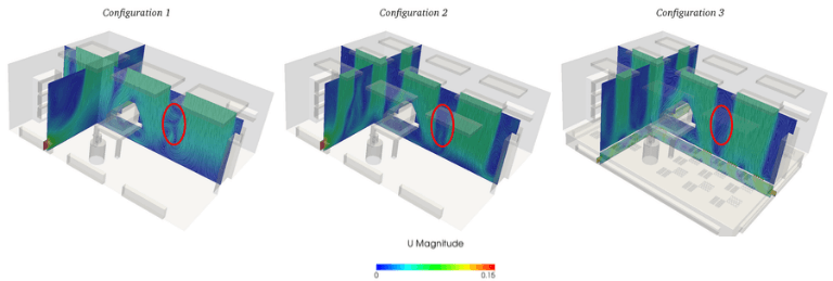
Cleanroom Ventilation Velocity Plot Comparison
All three cases are analyzed assuming the same conditions of inlet and outlet in order to make the results comparable. It can be seen that Configuration 1 has large recirculation in many regions, as marked in the following image. These are the zones where we try to avoid recirculation in order to avert the contaminant from spreading. Configuration 2 has comparatively less recirculation in critical zones. Finally, Configuration 3 has the least circulation, and the circulation is mostly concentrated in the corners of the domain.
Handling laminar and turbulent airflow principles might also be required in specific cases of cleanrooms, which can be analyzed using simulation. Laminar flow usually directs air downward with a constant velocity. This is usually applied over the entire ceiling to maintain a unidirectional flow. The laminar flow criterium is generally stated in portable workstations and is made compulsory in ISO 1 through ISO 4 classified cleanrooms [4].
Another important aspect to be noted is the ‘volume of air’ which is circulated. Certain equipment needs to operate under strict pressure and temperature conditions, which depending on the case, may be very high or extremely low (even vacuum pressure). Any uncontrolled conditions can give rise to an adverse and dangerous outcome. Maintaining the right pressure in the room can be achieved by controlling the air volume. A separate simulation of air handlers can be performed to study the volume of air discharged into the cleanroom environment. In some cases, these cleanrooms are operational 24 hours a day, all throughout the year. Hence ‘pressure drop’ is a factor which can be controlled in the design in order to maintain the conditions inside.[5].
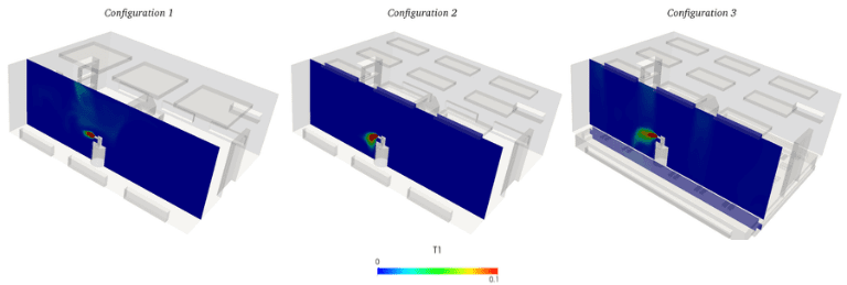
Cleanroom Ventilation Contaminant Spread Comparison in a Cleanroom Environment
People working in a cleanroom environment face the risk of exposure to chemical vapors if there is any mishandling of chemicals. To approach this problem let’s assume a particular source of contamination and analyze how it spreads in the room. The ultimate aim is to obtain a flow to get rid of the contaminant by regulating it directly to the outlets. To analyze the results, a particular plane is considered along the cross-section where the contaminant source is present, after which its path is studied.
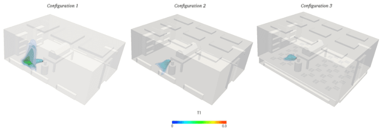
When a contour plot is created, it can be observed that the contaminant spreads along the walls and reaches the room ceiling in Configuration 1.
This can be explained by the recirculation of air as seen during velocity comparison. In the next case, the contaminant tries to approach the exhaust, since the source is placed near the side outlet. This might not have been the case if a different point of contaminant source is assumed far away from the outlet. There is even a possibility of recirculation.
In Configuration 3, the contaminant is exhausted down through the floor tiles and approaches the outlet under the flooring. Hence, a similar result can be expected regardless of where in the room the contaminant source is located. From this comparison, we can conclude that Configuration 3 is the winner!
Cleanroom Conclusion
It can be seen that HVAC solutions play an important role in designing cleanrooms and achieving an overall energy efficient model. This can be critical for lowering operating costs. Some of the measures to increase energy efficiency include reducing exhaust, room size, room air leakage, pressure drop, and simultaneous heating and cooling. All of these can be analyzed using engineering simulation and, in particular, CFD software.
This study illustrated the way simulation can aid you in achieving the best possible design. In this context, the term best design depends on various circumstances and in reality, there are many tiny factors which could adversely affect the system. It is our responsibility to ensure a safe environment for our fellow researchers working in cleanrooms.
Download SimScale Features Overview to learn more about the SimScale platform and its engineering simulation capabilities.

References
- https://en.wikipedia.org/wiki/Cleanroom
- https://www.ispe.org/index.php/ci_id/51599/la_id/1.htm
- https://www.ashrae.org/education-certification/instructor-led-courses/basics-of-cleanroom-design
- https://www.cleanairtechnology.com/cleanroom-classifications-class.php
- Environmental Systems Corporation, www.e-s-c.com


