This article covers the tips & tricks regarding a transient convective heat transfer simulation.
Please visit the documentation page to learn more about the Convective Heat Transfer Analysis type. In addition, you can check out the following convective heat transfer tutorials:
Solution
1. CAD Cleaning
Following points are essential:
- Firstly, avoid sheet/surface elements. The CAD model should only consist of solid parts.
- Secondly, avoid overlapping solids (unless they represent cell zones).
- Finally, avoid any CAD faults. This article explains how to find faults.
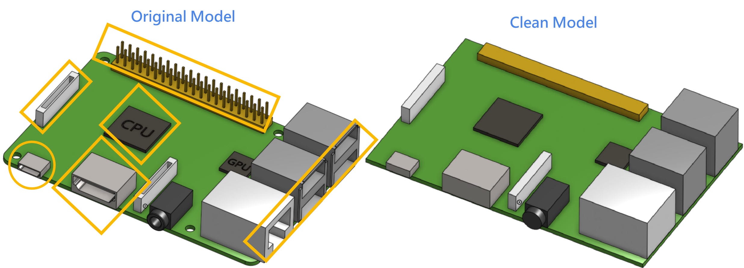
- Model only the essential parts. In other words, remove extra or unnecessary features/components. (small nuts, bolts, pins, etc.).
- Fill leftover holes and gaps.
Every detail has an influence on the performance, but ask the following question to yourself: Does this detail have a significant impact on the results?
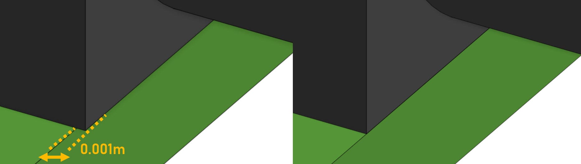
Finally, choose a minimum size and adjust the small edges to this specific size. Having a standard minimum thickness will later help you in the meshing stage.
2. CAD Preparation
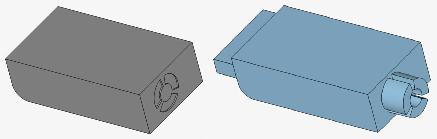
Convective heat transfer analysis examines the fluid. We need to create the fluid domain and get rid of the solid parts. Electronics equipment is often designed with a casing. No matter what you are analyzing, do the following:
Extract the Fluid Region
If forced convection takes place, extrude the inlets and outlets (usually 3-5 times the hydraulic diameter of the channel). This is not a must, but highly recommended for the solver stability.
In addition, if you need to know more information regarding the CAD preparation, visit this page.
3. Simulation Setup
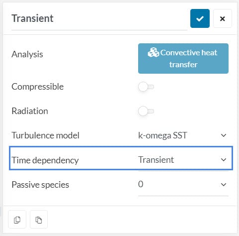
- Transient simulations are computationally expensive. First, ask yourself whether your problem requires a time-dependent analysis or not. As an example, if you would like to see the maximum or minimum temperature the system will reach under stable conditions, choose steady-state. If you precisely need to see the conditions within a specific time limit, then select Transient time dependency.
- Depending on the complexity you want to reach, you can include compressibility or radiation effects too. These details will increase simulation time and costs.
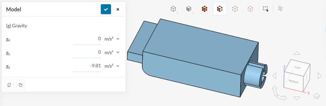
4. Model
Gravity should be defined with respect to global coordinate system.
5. Material Assignment
Depending on the compressibility assignment in the simulation setup, expected material properties vary. You can use SimScale’s default material library for common materials. For the others, you can use the default materials as guidance to apply the properties of the fluid you are planning to use.
For more information about the thermal properties, check the documentation page. In addition, you can check this knowledge base article to see how to create custom materials.
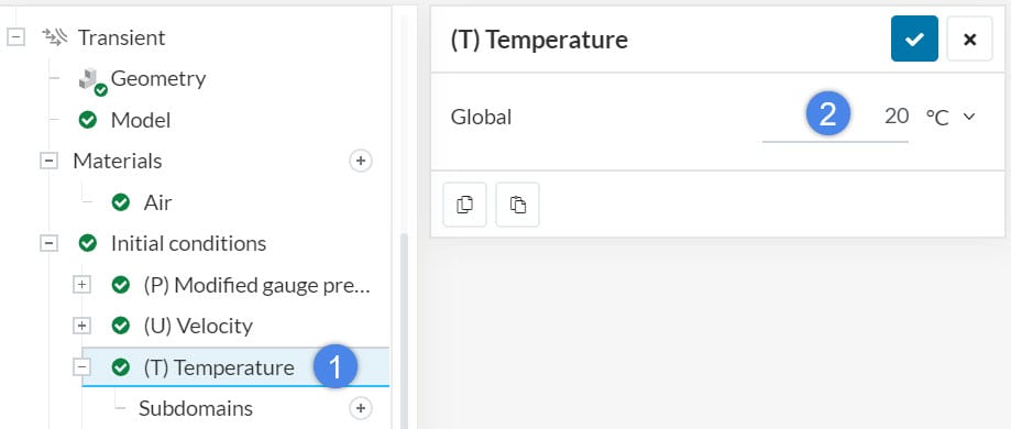
6. Initial Conditions
Define the initial temperature of the fluid domain. To clarify, the Temperature section is a quick way to assign temperature values on the whole fluid region. Moreover, you can create a subdomain to define the initial temperatures in specific regions.
7. Boundary Conditions
You can find the available boundary conditions for heat transfer analysis on this page. In this article, you will learn about the commonly used boundary conditions for transient heat transfer analysis.
7.1 Natural Convection Inlet/Outlet
If you expect the natural convection effects to dominate the flow at the inlet and outlet, use Natural Convection Inlet/Outlet Boundary Condition.
7.2 Custom – Fan Boundary Conditions
You can use custom boundary conditions to assign an inlet or outlet fan. Check out the thermal management tutorial to see how to assign a fan curve.
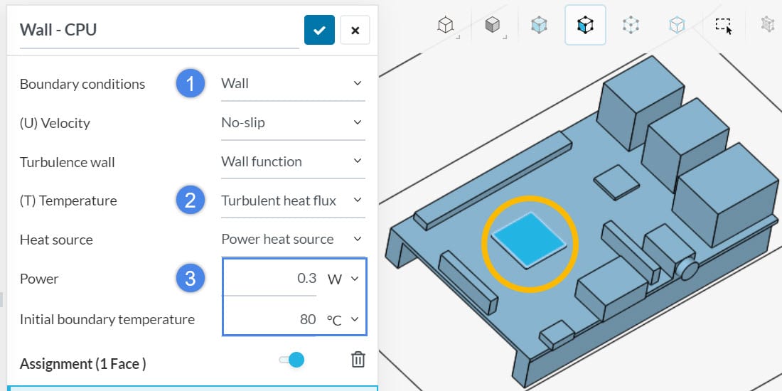
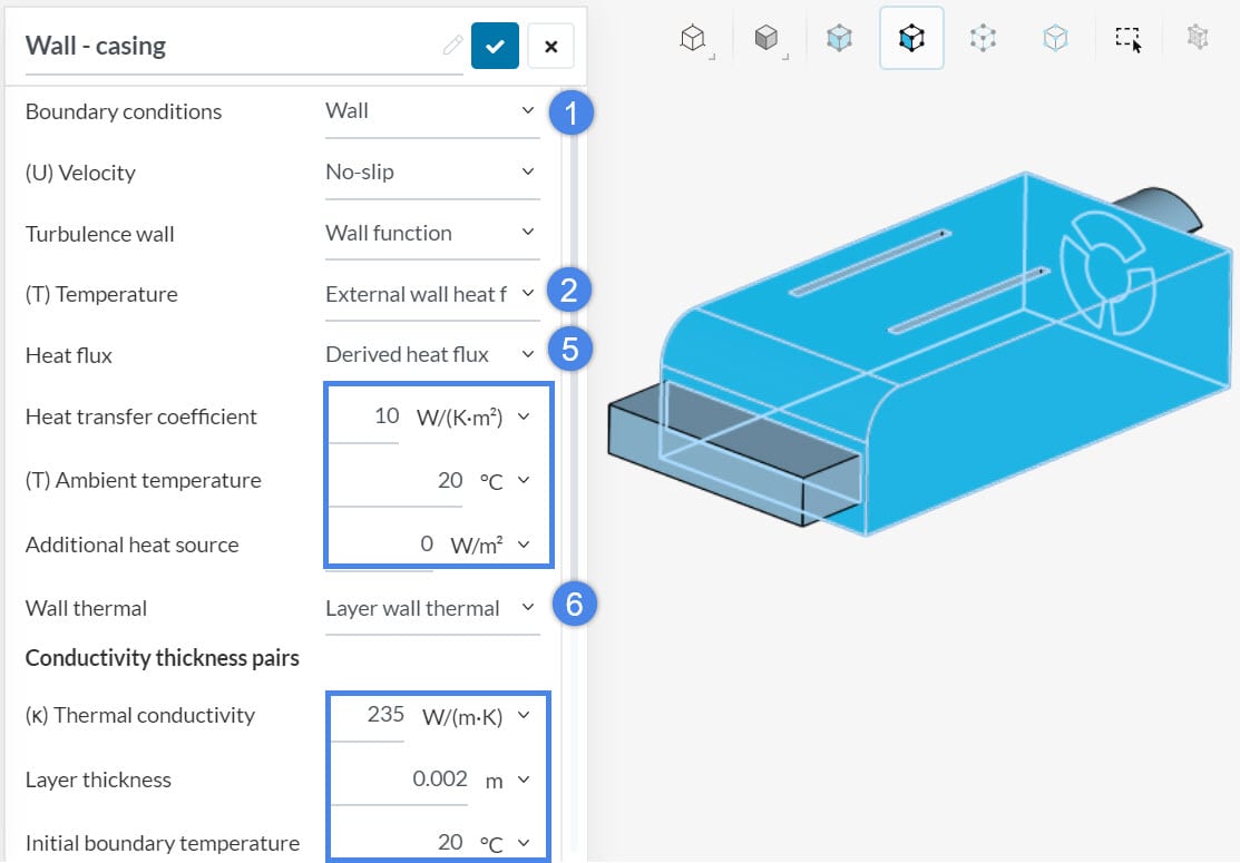
7.3 Wall Boundary Conditions
You can use a wall boundary condition to define the heat dissipation from the component surfaces.
If the thermal conductivity within the casing is also an important parameter, you can use the wall boundary condition to assign convective heat transfer effects and the thickness of the casing material. Check out this article to learn more about thermal wall conditions. In addition, you can use the empirical approximations or visit this website to approximate the convective heat transfer coefficient.
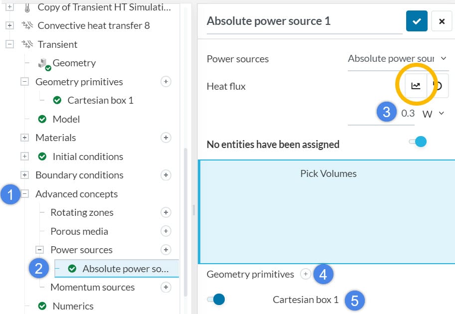
7.4 Power Sources
You can use this boundary condition to define the volumetric heat generation. In a transient analysis, you can define the heat generation as time-dependent. The table assignment is just as explained in the transient heat transfer article.
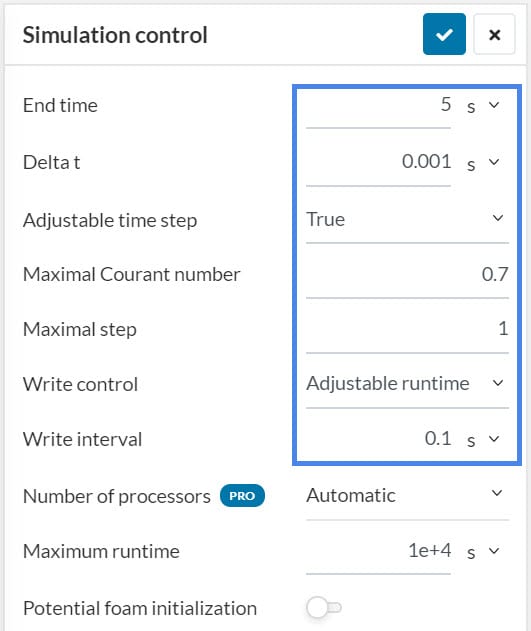
8. Simulation Control
The time control settings are very important in transient convective heat transfer simulations. Follow the steps:
- Define the End time of your simulation.
- For stability reasons, start the simulation with a very small time step.
- Keep the Adjustable time step option toggled on. This will automatically adjust the time step length, with respect to the courant number.
- Define the maximum courant number. We recommend keeping this below “1” for stability and accuracy concerns. However, small courant numbers may lead to very small time steps. If the speed is important, you can also increase the Courant number to a very large value, but keep in mind that this means giving up from the stability and accuracy. Check this article to learn more about the courant number and its influence on simulation time.
- Limit the maximum time step by defining the maximal step
- Choose a write control that works best for you. This option defines how often the results should be saved. The smaller this number the more intermediate results, and the less performant the post-processor.
- Define a maximum runtime. With this option, you can limit the simulation time.
The following settings show that we were simulating the thermal response of the first 5 seconds. Simulation results were saved every 0.1 seconds. Maximum runtime 1000s is going to stop the simulation if it takes more than two and a half hours.
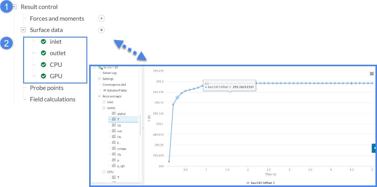
9. Results Control
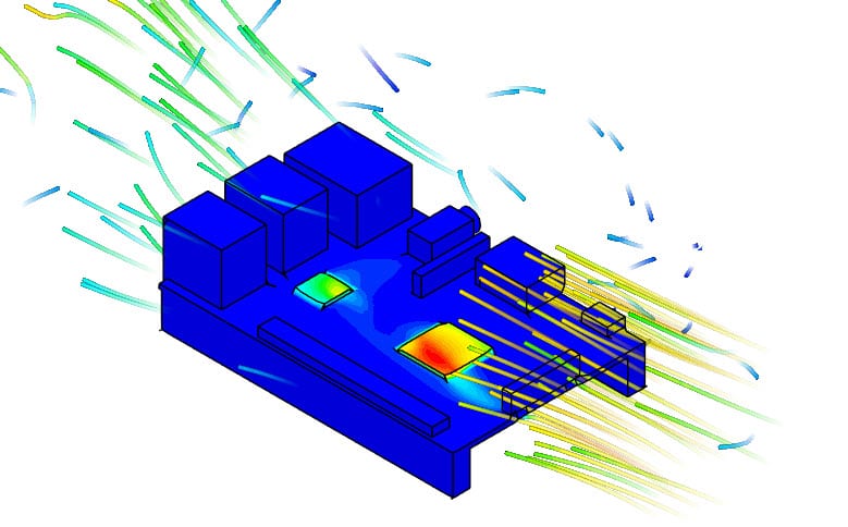
Always add result control items, because you can track the quantitative data with respect to time and download it as a .csv file. The graph below shows the outlet temperature of the transient convective heat transfer simulation with respect to time.
10. Meshing
Meshing is the most crucial part of transient simulations because it significantly affects the simulation time step, thus the time simulation takes. The Courant number is correlated to the fluid velocity and the cell size. The smallest cell size will most likely define the time step of the simulation. Therefore, we need to keep the cell size as coarse as possible.
Although we recommend using the Standard mesher for most of the applications, it is not the best choice here. Standard mesher generates fine cells to capture the CAD details. We don’t have control over the smallest cell size! Similarly, the Hex-dominant mesher generates fine cells to capture the features properly. Therefore, automatic meshers are not recommended.
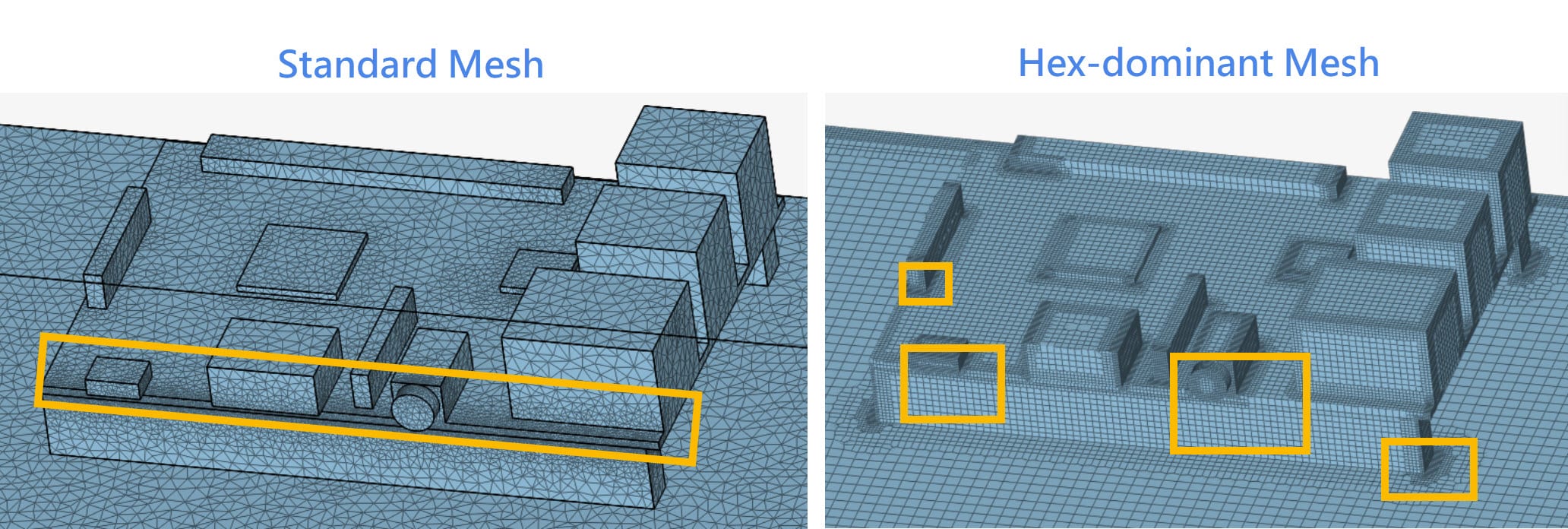
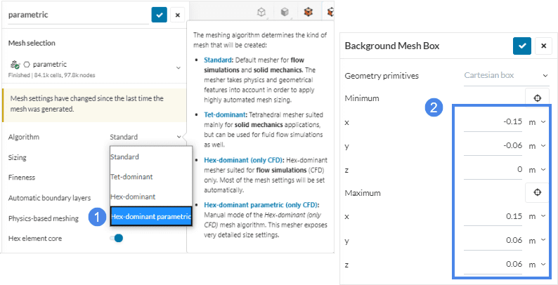
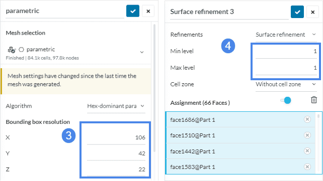
The most suitable meshing algorithm in this case, is Hex-dominant Parametric. Using the Parametric mesher, the user has full control over the mesh sizing. You can see check out this article to learn how to use the parametric mesher. Do the following
- Keep the smallest cell as large as possible.
- Do not use any layer refinement.
- Keep the mesh uniform. In other words, avoid too many refinements.
The following workflow, represented in the figures, serves as an example of how to set up this mesh.
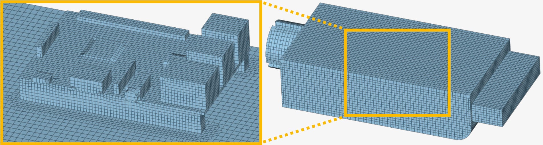
The result of a uniform parametric mesh will look as follows:
Summary: Best Practices for the Transient Convective Heat Transfer Simulations
- Use Hex-dominant Parametric mesh algorithm.
- If you want to stick to the standard mesh algorithm, use manual sizing. Then, assign the minimum thickness as zero. Finally, use local refinements to control the cell size.
- The smallest cell size will most likely determine the simulation speed, therefore choose it as coarse as possible.
- Assign the Courant number as 0.5 if the accuracy is important.
- Use a very large (up to 100) Courant number if the speed is important.
Note
If none of the above suggestions solved your problem, then please post the issue on our forum or contact us.


