CAD Cleanup is mostly different for any CAD so there is no “golden rule” that guarantees success, but there are some important rules and tricks. This article describes some general rules/standards required for CFD simulations and best practices on how to find faults in cad models so that you have a starting point.
This content provides an overview of everything that is necessary for preparing a CAD for simulation.
Approach
There are two main rules which are crucial for any flow simulation:
- Your CAD needs to be watertight: There must not be any holes except inlets and outlets.
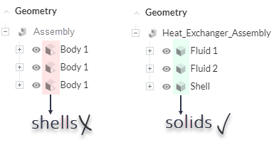
- Your CAD must only contain solid parts. Shells or Sheets must not appear. The following picture demonstrates, what the geometry tree should look like after the upload:
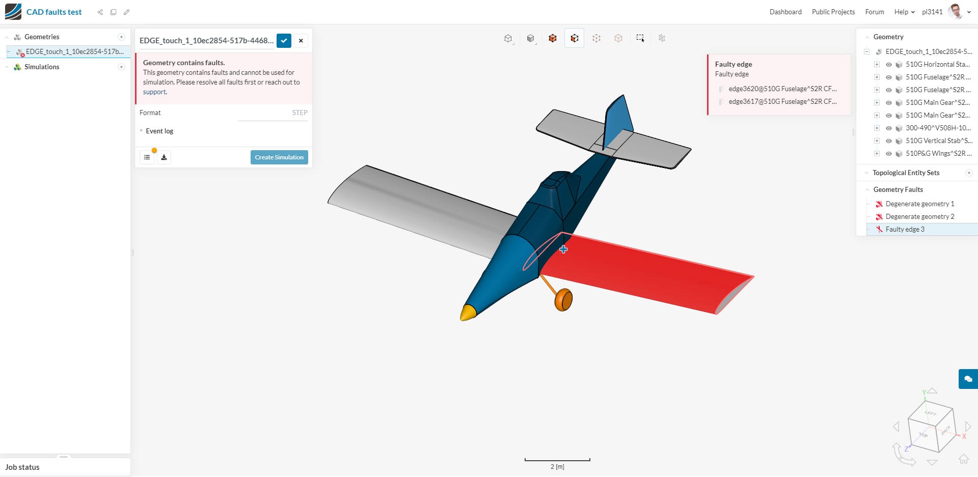
SimScale highlights the regions where the CAD is faulty. The picture below shows an example:
In general, you should avoid intersecting parts (this is crucial for CHT simulations), warped surfaces, too small entities.
Expected Outcome
The end result should be a CAD model that consists of only solids. The fewer solids the better, so merge as many parts as possible.
Best Practices
Tip 1: Merge Everything
If you have more than one part and they are supposed to touch/intersect, then try to merge them. CAD tools normally highlight regions where it fails to merge. These are most likely the regions that are causing the problem.
Generally, merge as much as you can. This simplifies the simulation.
Tip 2: Convert Sheets to Solids
Try to fill the gaps. In most cases, the sheets already show how the solid would look like, but there are holes that need to be closed in order to get a solid part.
The following list provides basic workflows for how to convert “surface to solid” in some of the most commonly used CAD tools. It might not be accurate for specific functionalities.
- SpaceClaim: Stitch the surface to convert it to a solid part
- Onshape: Add “Thickness” to the surface and merge them
- SolidWorks: Have a look at this video.
- CATIA: Have a look at this video.
- Autodesk Inventor: Have a look at this video.
Tip 3: Watch out for Model Tolerance
A model tolerance comes directly from the CAD kernel of imported geometry. Computers aren’t perfect, so vertices and edges each have a tolerance that can be imagined as a bubble. Any two components in the same bubble will be merged, and appear as one. This ensures that all models are closed, even if the numbers aren’t exactly equal.
Although the model tolerance will help ensure closed 3D geometry, there can be problems that arise as well. A mesh can never be refined past the model tolerance, and a factor of safety of 10 is automatically included. If you try to refine a mesh beyond the model tolerance, this error will appear in the meshing log:
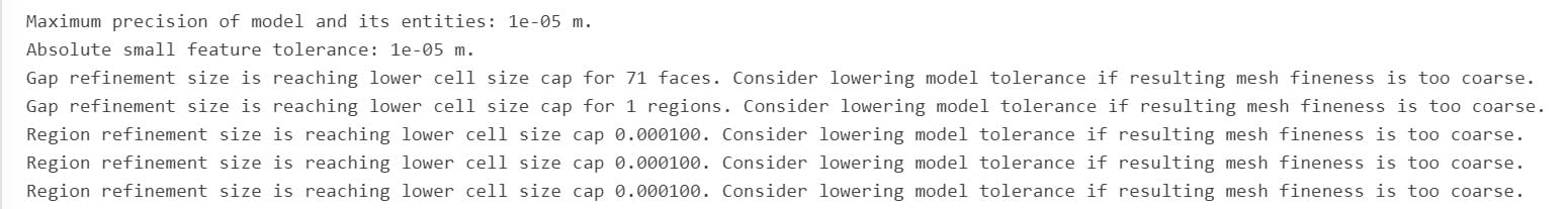
If you are seeing this problem in the meshing log, you can try to improve the CAD data while importing it to the SimScale platform.
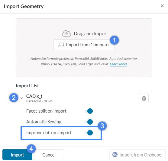
When “Improve data on import” is active during the CAD upload, we reduce the tolerances to the minimum possible, meaning the smallest bubble around each vertex without changing the model topology. This makes it possible to create a finer mesh and often provides a viable solution. However, the CAD upload can take a considerable amount of time when this option is used in very complex models. Therefore you may opt-out and reconsider in case you face issues in geometry handling or meshing.
This feature is active as default in the CAD upload process, therefore the majority of these problems should have already been solved automatically. If this doesn’t help, some CAD tools also provide solutions. Check your CAD tools optimization functionality. Many CAD tools have “optimize edges” or similar features to optimize model tolerance.
If the above solution does not work the only solution is to make changes to the geometry using our CAD mode or within your CAD package.
Note
If none of the above suggestions solved your problem, then please post the issue on our forum or contact us.


