
Validation Case: 3D Punch With Rounded Edges (NAFEMS Contact Benchmark 2)
This 3D punch contact validation case belongs to solid mechanics. This test case aims to validate the following parameters:
- Penalty contact
- Friction
The simulation results of SimScale were compared to the analytical results derived from [NAFEMS_R94]\(^1\).
Geometry
The geometry consists of a punch (DGHIJK) on top of a foundation (ABCDEF). The 3D punch has a 10 \(mm\) radius fillet at the edge of the contact with the foundation. Figure 1 shows a wireframe of the geometry:
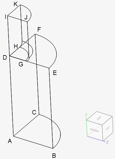
Due to the symmetry of the problem, only a quarter of the model is used for the simulations. These are the coordinates for each of the points:
| A | B | C | D | E | F | G | H | I | J | K | |
| x \([mm]\) | 0 | 0 | 0.1 | 0 | 0 | 0.1 | 0 | 0.04 | 0 | 0 | 0.05 |
| y \([mm]\) | -0.2 | -0.2 | -0.2 | 0 | 0 | 0 | 0 | 0 | 0.1 | 0.1 | 0.1 |
| z \([mm]\) | 0 | 0.1 | 0 | 0 | 0.1 | 0 | 0.4 | 0 | 0 | 0.5 | 0 |
The following dimensions are used in the creation of the geometry:
| Geometry Feature | Dimension \([mm]\) |
| Punch diameter | 100 |
| Punch height | 100 |
| Foundation diameter | 200 |
| Foundation height | 200 |
| Fillet radius at the edge of the punch contact | 10 |
Analysis Type and Mesh
Tool Type: Code_Aster
Analysis Type: Dynamic
Mesh and Element Types: The meshes used in this project were created in SimScale with the standard algorithm.
| Case | Element Type | Nodes | Element Technology | Solution Method | Contact Smoothing | Penalty Coefficient | Coefficient of Friction |
| A | 1st Order Tetrahedral | 32101 | Standard | Penalty | On | 1e14 | 0 |
| B | 2nd Order Tetrahedral | 50226 | Reduced Integration | Penalty | On | 1e14 | 0 |
| C | 1st Order Tetrahedral | 32101 | Standard | Penalty | On | 1e14 | 0.1 |
| D | 2nd Order Tetrahedral | 50226 | Reduced Integration | Penalty | On | 1e14 | 0.1 |
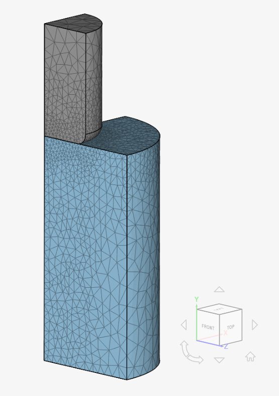
Find below the mesh used for cases B and D. It’s a standard mesh with second-order tetrahedral cells.
Simulation Setup
Material:
- 3D Punch
- Material behavior: Linear elastic
- \(E\) = 210 \(GPa\)
- \(\nu\) = 0.3
- \(\rho\) = 7870 \(kg/m³\)
- Foundation
- Material behavior: Linear elastic
- \(E\) = 70 \(GPa\)
- \(\nu\) = 0.3
- \(\rho\) = 7870 \(kg/m³\)
Boundary Conditions:
- Constraints
- \(d_x\) = 0 on faces ABED and DGJI;
- \(d_z\) = 0 on faces ACFD and DHKI;
- Fixed support on face ABC.
- Surface loads
- Pressure = \(10^8 \ Pa\) on face IJK.
Result Comparison
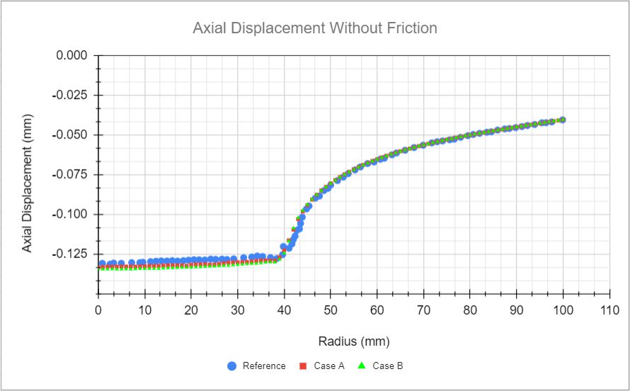
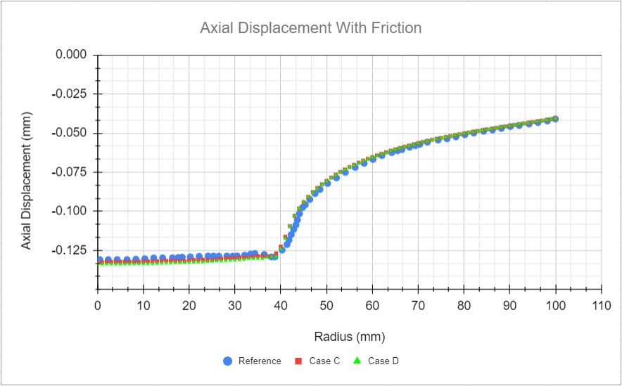
Comparison of the displacements and the normal pressure of the nodes on edge DE. The values of reference in all figures were calculated with MSC.MARC and extracted from [NAFEMS_R94]\(^1\) with WebPlotDigitizer.
The first plot is a comparison between the axial displacements from the cases without friction and the reference values:
Now, comparing axial displacement from the cases with the friction and the reference values. Similarly to the previous case, a very good agreement is observed here:
Now, still analyzing the results over the DE edge, we will compare the radial displacements obtained with SimScale to the reference ones.
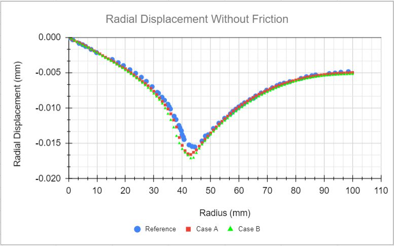
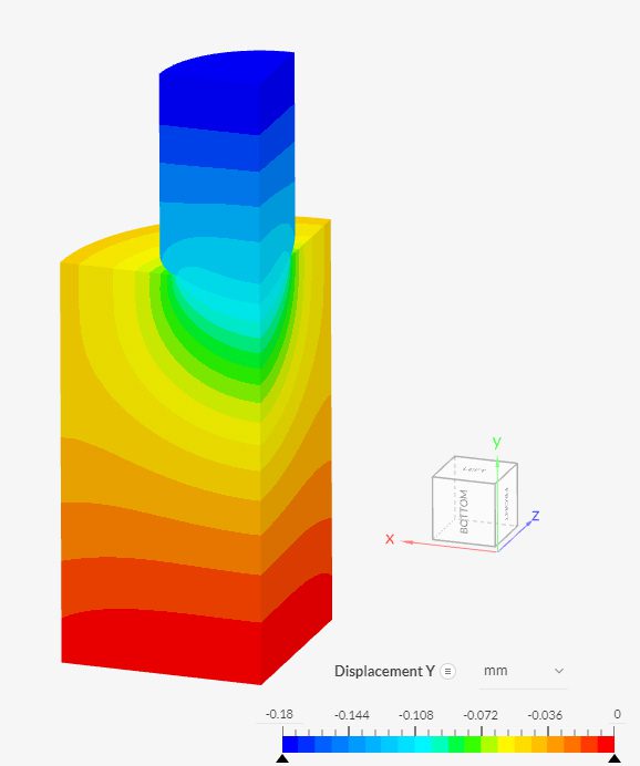
Figure 6 shows contours for \(y\) displacement, in meters, for case D:
References
Last updated: September 30th, 2021
Did this article solve your issue?
How can we do better?
We appreciate and value your feedback.






