There is an increase in the use of CFD validations, especially for Architectural designs from Revit. Therefore, it is important to know how to prepare Revit models to run a Pedestrian Wind Comfort Analysis (PWC). Read more about how to bring in Revit models to SimScale below.
SimScale provides a dedicated and easy to setup module for Pedestrian Wind Comfort Analysis. More about the Pacefish®\(^1\) PWC analysis using SimScale can be found here.
Objective
This article revolves around the workflow on how to open Revit files and define the scope of the model, including the terrain creation. This way we can ensure to create a valid CFD-ready model from Revit.
Revit to SimScale Workflow
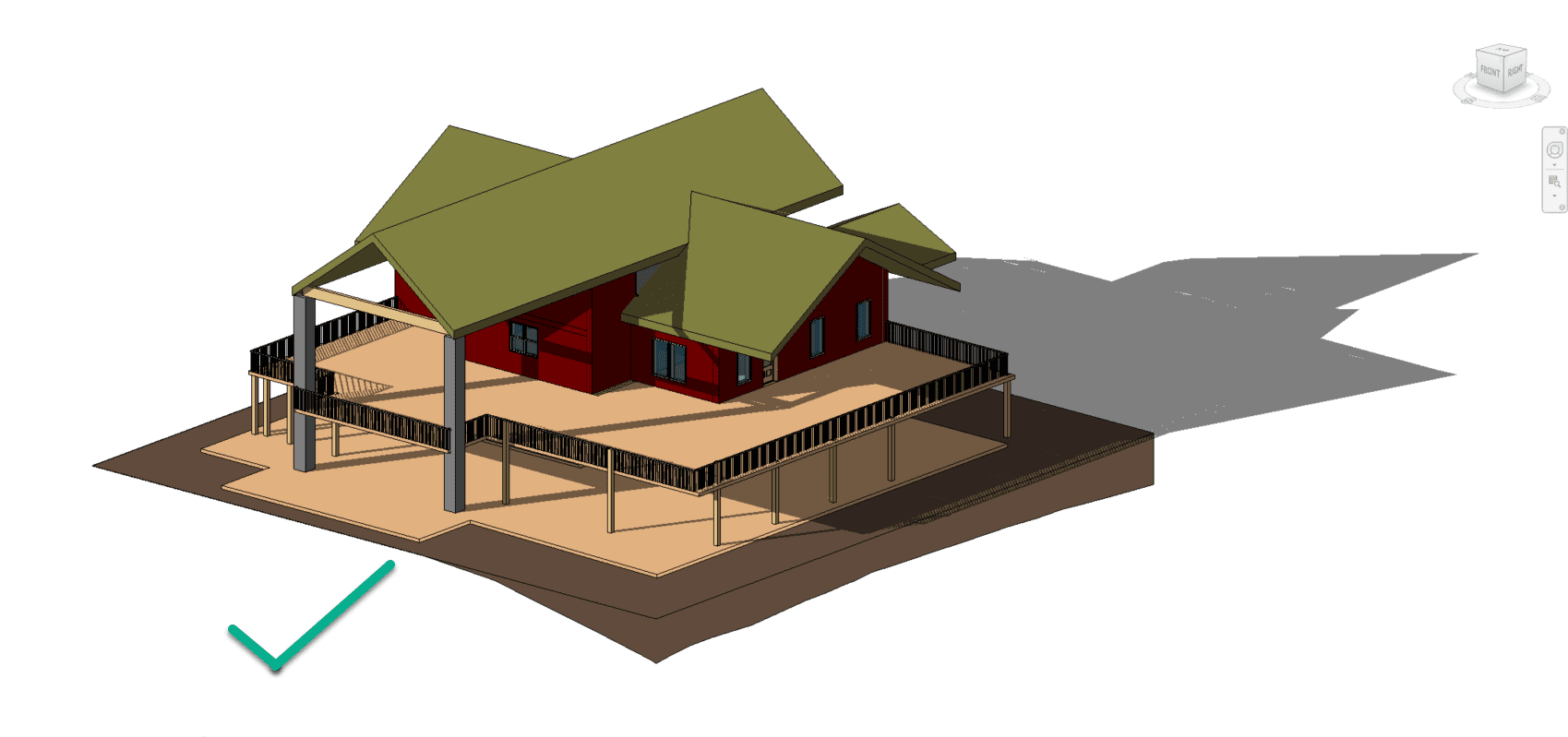
To explain the workflow, a detailed house geometry from Revit takes as an example:
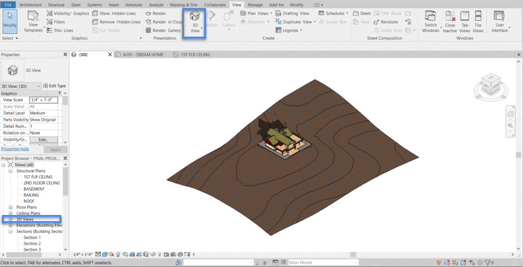
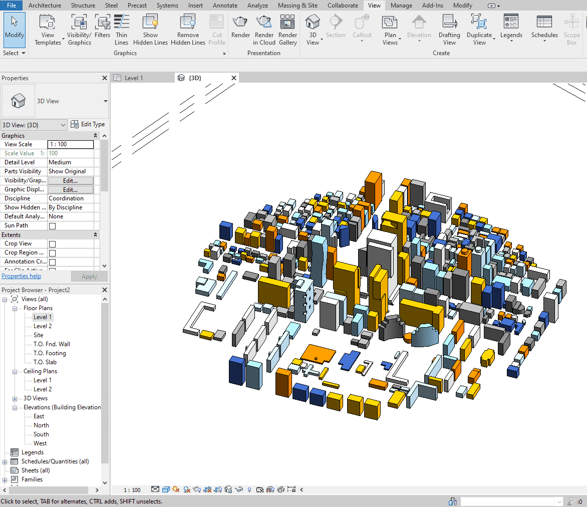
By default, Revit opens a model in Structural plans mode. The 3D view can be accessed using View –> 3D as shown in the image below.
Cleaning the Model for External Wind Analysis
Generally, Revit models come with a lot of details. But for an efficient external CFD analysis, some of the details/components are not necessary. This section shows how to identify them in the model and hence, defining the final scope of the model.
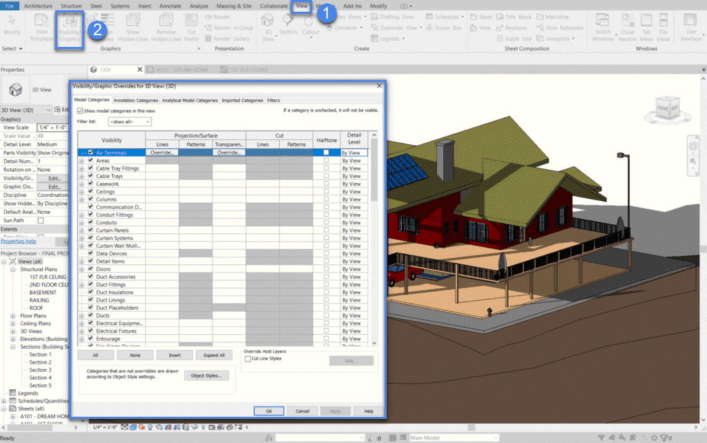
To browse through the components present in the model, Visibility Graphics can be used. To access the same select ‘View –> Visibility / Graphics’ as shown below:
An external wind analysis would need only the basic components which define the shape and topography of the building(s) to be analyzed. Hence, it is encouraged to check the elements or parts necessary for the analysis.
Here is a list of important items necessary for a CFD simulation:
- Ceilings
- Columns
- Curtain panel, Curtain system
- Walls
- Topography
- Floors
- Masses
- Roofs
- Site
Except for the above-mentioned items/groups, other items can be turned off. To make this effective in the 3D viewer, press ‘Apply’.
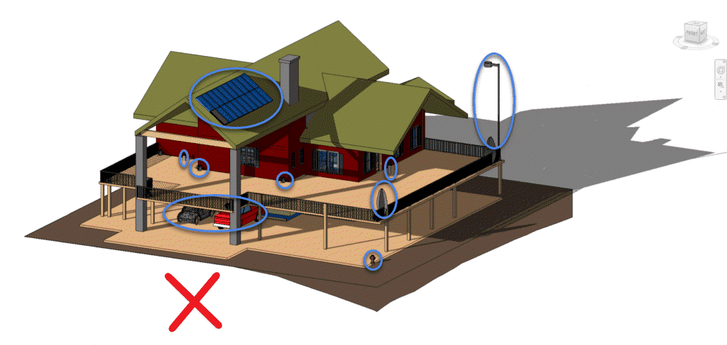
Best Practice
For external wind analysis, we won’t need the furniture, pipes, fittings, duct accessories, electrical equipment, doorbells, safety systems, wires, etc. In general, things that are relatively smaller in dimensions (<0.5 \(m\)) are not encouraged.
Terrain Creation
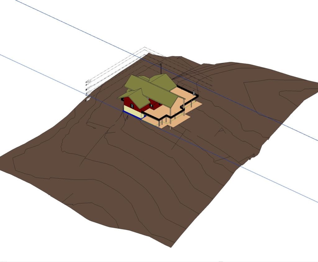
Oftentimes, a Revit model includes the buildings, but not the topology of the surroundings, such as the geometry below:
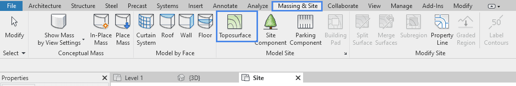
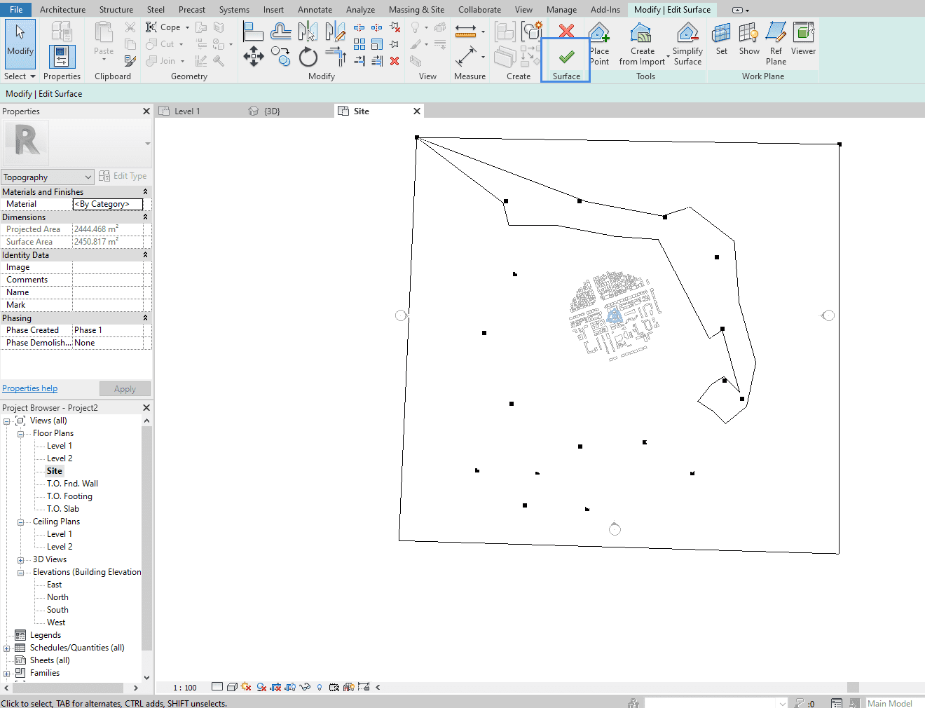
If the buildings are present at different heights, it is recommended to capture such differences by adding the terrain to the CAD model. In Revit, the terrain can be constructed by using the Toposurface tool under Massing & Site:
Once inside the Toposurface tool, the user can define points with different Elevations to define their terrain. Points can be manually defined with Place Point. Alternatively, it’s also possible to use a pre-defined .csv file by clicking on Create from Import.
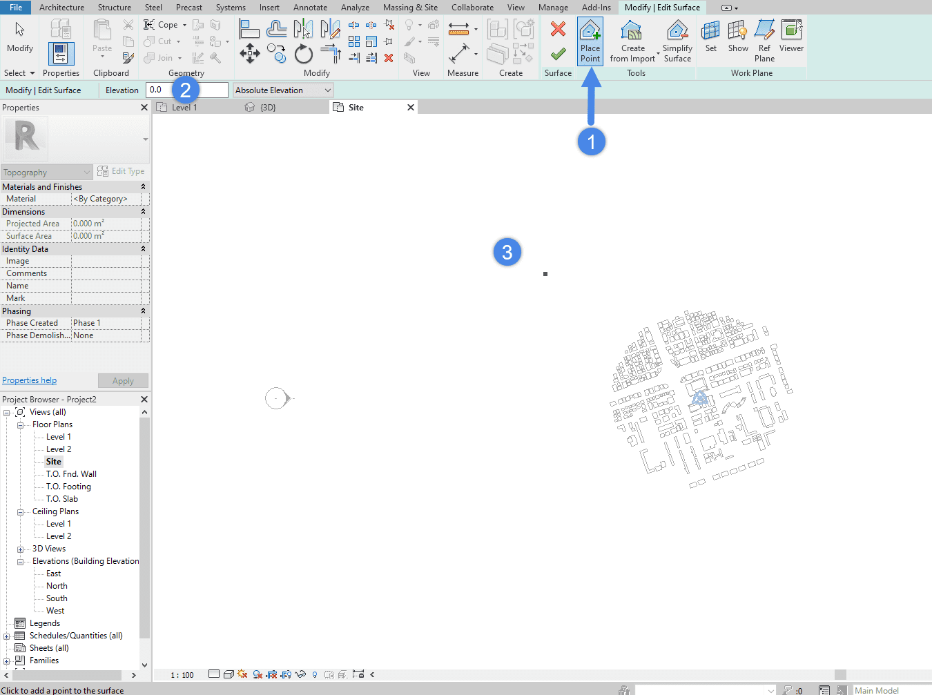
- Activate the ‘Place Point’ feature
- Adjust the Elevation of the next point
- Click on the viewer to set a point
As a best practice, the terrain used for a PWC simulation should be wider than the computational domain, so it’s important to extend the terrain much farther than the region of interest. The objective is for the terrain to be wider than the computational domain in all directions.
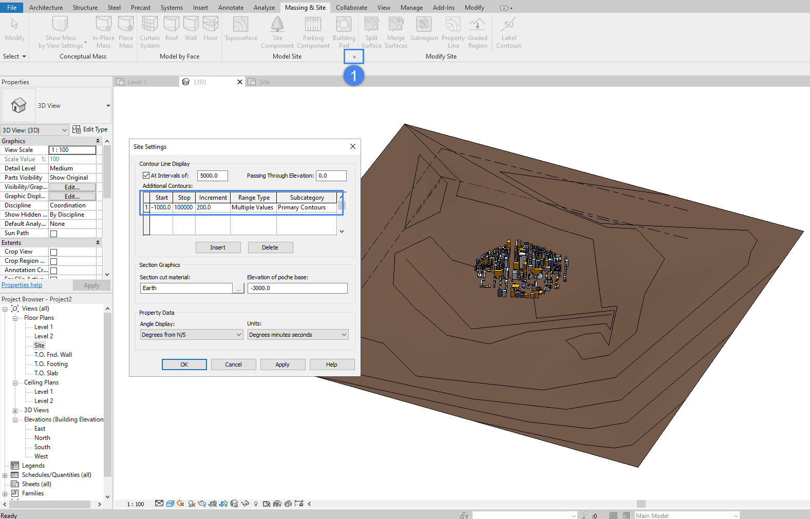
The best way to inspect the resulting terrain is from a 3D view. Adjusting the height contour settings may also improve the visualization:
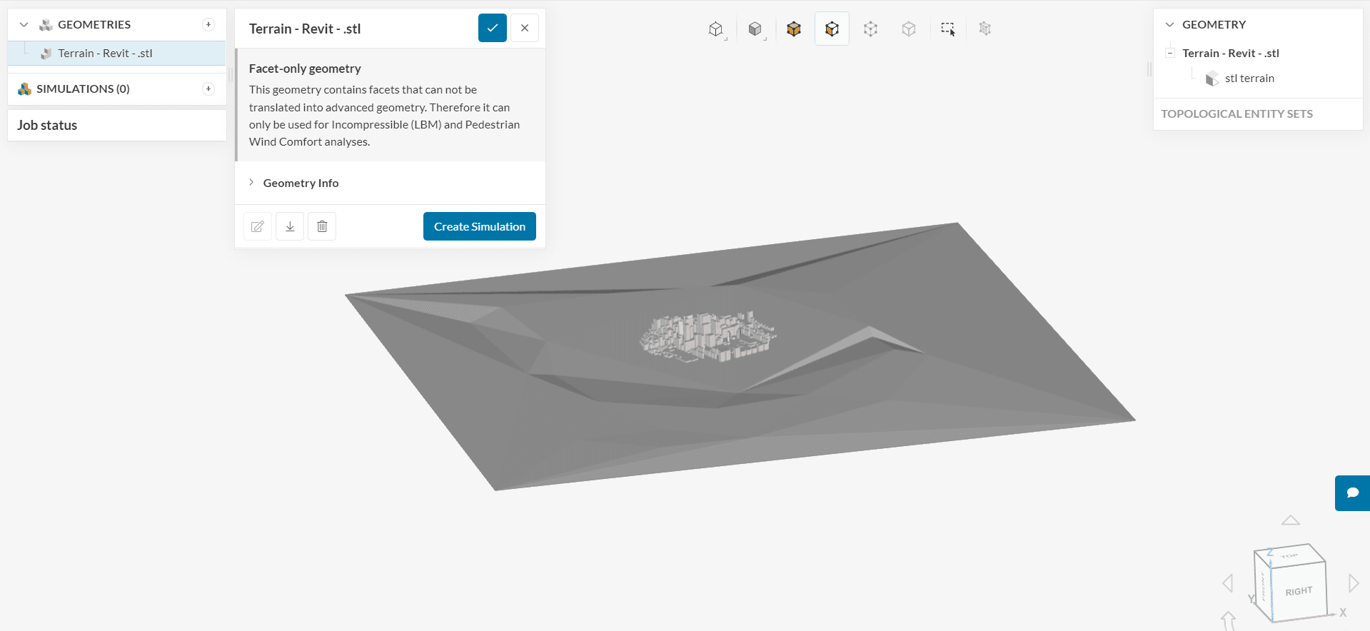
Finally, the resulting model can be exported from Revit as a .stl geometry and imported to SimScale for simulations.
To know more about general CAD requirements for External Wind analysis check the following article:
References


