Pedestrian wind comfort (PWC) analysis in SimScale, is based on the lattice Boltzmann solver (LBM) developed by Pacefish®\(^1\). This short article explains the best practices to be followed while dealing with the geometry in PWC simulations.
Geometry Details
Although the geometry doesn’t need to be cleaned for LBM, files larger than 1 Gb rarely need to be that large. SimScale will likely be able to upload very large files, typically up to around 3 Gb, however, the experience will be slow and you could face some problems in simulation. For this reason, it is strongly recommended to look for the root cause of a heavy file. In the past, files have been reduced from +8 Gb to less than 200 Mb by removing details in signage, banners, and fences.
As a general rule, in PWC, features less than 0.3 \(m\) are unlikely to make a difference and should be removed at your discretion.
Significant Gaps
SimScale’s LBM solver deals with small gaps in geometry very well so water tightness is not required, however, if a gap is significant, and fluid can freely pass through, you can expect the solver to solve the simulation. This may affect results, however. This is particularly important if the gap is located near the region of interest. These gaps could be missing faces or even that a building is not intersecting the topology and is, therefore, hovering over the surface allowing fluid under it.
Although LBM is incredibly robust, we need to be responsible when checking geometry, and if results look strange or unexpected, inspect the geometry in that region for gaps. In the past these were due to missing faces in the architectural model of the main building, missing faces under bridges, and surrounding buildings not being extruded through the terrain.
Screens, Trees, and Vegetation
It’s important to represent any screens, trees, or vegetation as a closed volume region. It is commonly seen that trees are imported from a BIM tool where trees are represented as two, 2D perpendicular outlines of trees. These should be removed as they incorrectly represent the actual flow. In this case, it’s better to not have them, or replace them using a solid representation.
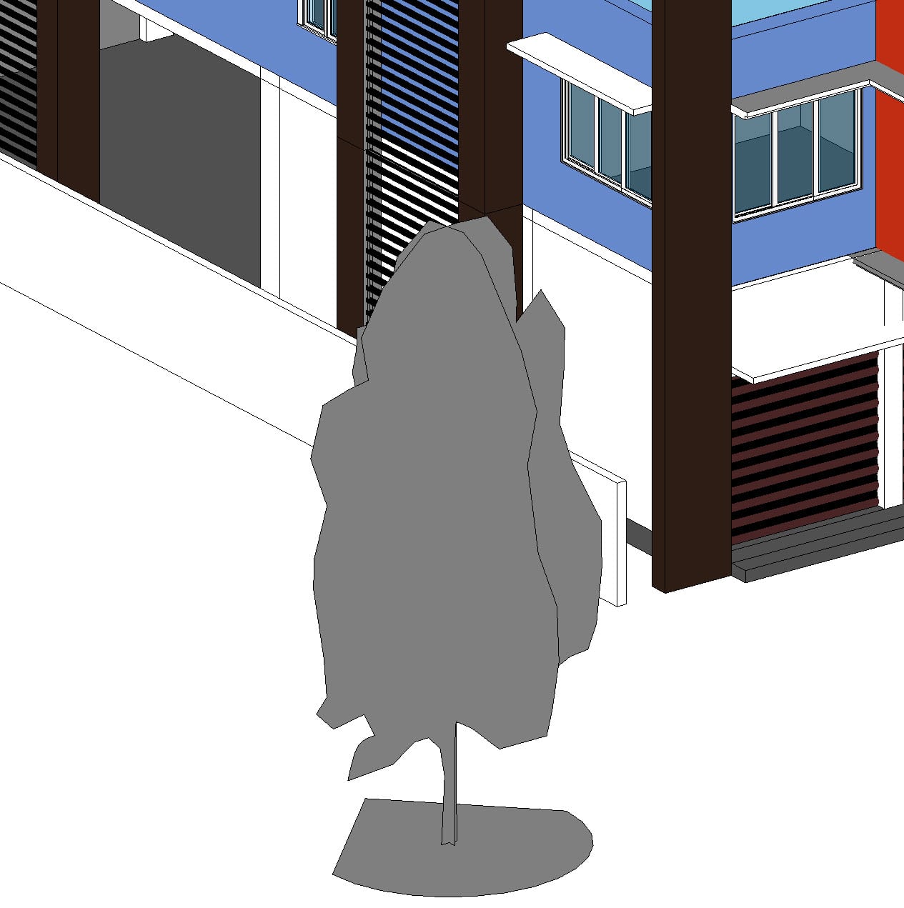

The above figures clearly show the difference between the two, and what is and isn’t acceptable.
To define the tree as a porous object (air can flow through and around it) you simply select the solid representing the foliage (top green volume in the image above). Learn more about using porous media here.
While screens, railings, and fences are often detailed in the geometry, there are a few things that make this less than ideal. Firstly, the geometry upload becomes heavy and slows the upload and preparation process. This can also affect the responsiveness of the SimScale platform leading to a strained user experience.
The second issue here is that if the detail is smaller than the cell size, the geometry may be treated as a wall or ignored leading to inconsistent results. Therefore, a better approach is to model the small geometry as a porous media which is the technical name for modeling repetitive geometry that is significantly smaller than the cell size.
Screens can be represented as thin 3D volumes. To ensure that the screen is correctly modeled however, the mesh should have at least one cell in its volume. Therefore, the user should consider the actual depth of the volume, as a very thin volume will require an extreme refinement and is likely to increase the solving cost by an order of magnitude. In most cases, a thicker than physical volume is acceptable to model through-plane effects correctly, and only in-plane effects are likely to see any reduction in accuracy.
Temporary Geometry
Temporary geometry includes people, cars, seats, tables, and other small items that are not a permanent fixture. This should be removed, as it can act as obstacles that affect the simulation results.
For example, fixed trash bins might be fixed, but in a year’s time, the Council may decide to replace, remove or move them, in which case the results of a PWC study would change, therefore they cannot be included.
Related Articles
Our Knowledge Base articles have a great collection of articles associated with CAD issues in PWC analysis. Explore them now!
References


