Region of Interest
The core functionality of the Region of Interest (ROI), in a Pedestrian Wind Comfort (PWC) simulation, is to define the area or the domain around the main building/region over which the pedestrian comfort should be evaluated. Additionally, it is used to automate the size and the orientation of the simulation domain reducing efforts drastically.
It is mandatory and an important step in the PWC analysis and needs to be accessed at the very beginning of the simulation just after importing the geometry.
Region of Interest Parameters
The ROI setup looks as follows:
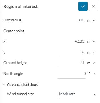
As can be seen from Figure 1, the parameters it includes are Disc radius, Centre point, Ground height, and North angle.
Additionally, under Advanced settings, there is the option to make the Wind tunnel size larger than the default or to make a completely customized wind tunnel by defining the extensions in each direction. These parameters are discussed in detail below.
Disk Radius and Center Point
Region of interest can only be specified in the form of a disk. Hence, Disk radius defines the radius of that disk that will be used to show the results of the simulation. As obvious, the Center point defines the center of that disk in x- and y-coordinates.
Ground Height
The Ground height (z) defines the level at which the floor of the wind tunnel is placed. There are two scenarios:
- In cases without terrain, this should simply be the ground level of the buildings – please ensure that all buildings have the same ground level to not have flow below the buildings (or in other words buildings hovering above the ground).
- In cases where the terrain is included in the geometry model, the ground height should be placed at the lowest level of the terrain that is within the analysis domain. If the ground height is selected too high, parts of the terrain might not be taken into account for the analysis as they would be placed below the virtual wind tunnel floor. If the ground height is selected too low, the simulation efficiency might not be ideal, as the virtual wind tunnel size will be more than necessary.
North Angle
All the geometries imported to the SimScale Workbench for a PWC analysis are, by default, aligned such that the +y axis represents the north direction. However, if this convention was not followed in the construction of your geometry, the angle (degrees/radians) may be altered here allowing for the north to be realigned.
Advanced Settings
Under Advanced settings, the size of the wind tunnel can be adjusted. For an automated approach, select ‘Moderate’ or ‘Large’. The dimensions used in these cases are:
Moderate:-
$$ H, S, I = 3h $$
$$O = 9h$$
Large:-
$$ H, S, I = 5h$$
$$O = 15h$$
where \(S\) is the side extension, \(I\) is the inflow extension, \(O\) is the outflow extension and \(H\) is the height extension. The height of the tallest building is defined by \(h\) (calculated from the Ground height specified above) and is taken from the CAD geometry information. This is indicated in the below diagram with \(r\) being the disk radius:

For more control, the user can select Custom under which the extensions described previously, \(H\), \(S\), \(I\), and \(O\) defined explicitly from zero (tight box around the region of interest) onward. Smaller wind tunnels will likely reduce accuracy and should be used with caution, the benefit being reduced computational resources and faster computing speeds. Customized settings should only be used by experienced users following best practices in wind sensitivity studies.
Important
Incompressible LBM and wind comfort simulations use a slightly extended domain compared to the original bounding box or wind tunnel size specified above. This slight extension is needed in order to obey the requirements of the underlying solver Pacefish®\(^1\) where the number of cells in x, y and z direction needs to be divisible by 4. In order to enforce this constraint, we extend the outlet face, extend the top face and symmetrically extend the two side faces. We pick the minimal extensions as possible to enforce the requirement.
Visually Inspecting the Domain
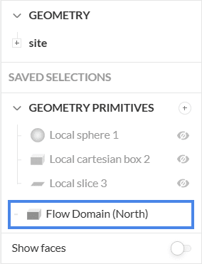
If a topology is present, it should extend beyond the limits of the wind tunnel for all wind directions. This can be done by clicking on the eye icon on the right end of the workbench (Figure 3) to visualize the flow domain/wind tunnel and observing the green disk in relation to the floor (Figure 4).
Important
As stated before, the default flow domain is shown in the north direction (+y axis) but will be rotated based on the number of wind directions specified for the analysis.

It is advised that the extension should be outside the green circle everywhere, which, in the above example is not true and should be revised. You can read more about why we stipulate this requirement here. Furthermore, you can read how to do this in Rhino with a worked example.
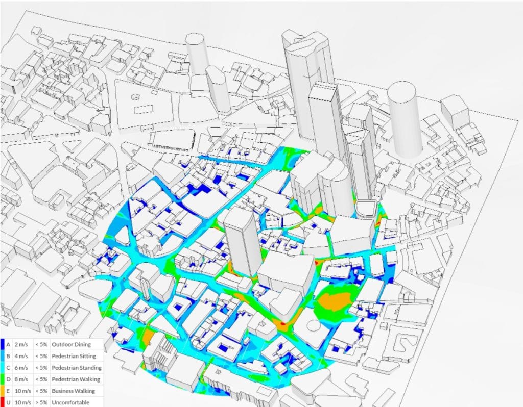
The wind comfort evaluation is done over the specified region of interest only, as shown in Figure 5:
References
Last updated: January 3rd, 2025
Did this article solve your issue?
How can we do better?
We appreciate and value your feedback.
What's Next
Wind Conditions in PWCpart of: Pedestrian Wind Comfort Analysis


