Documentation
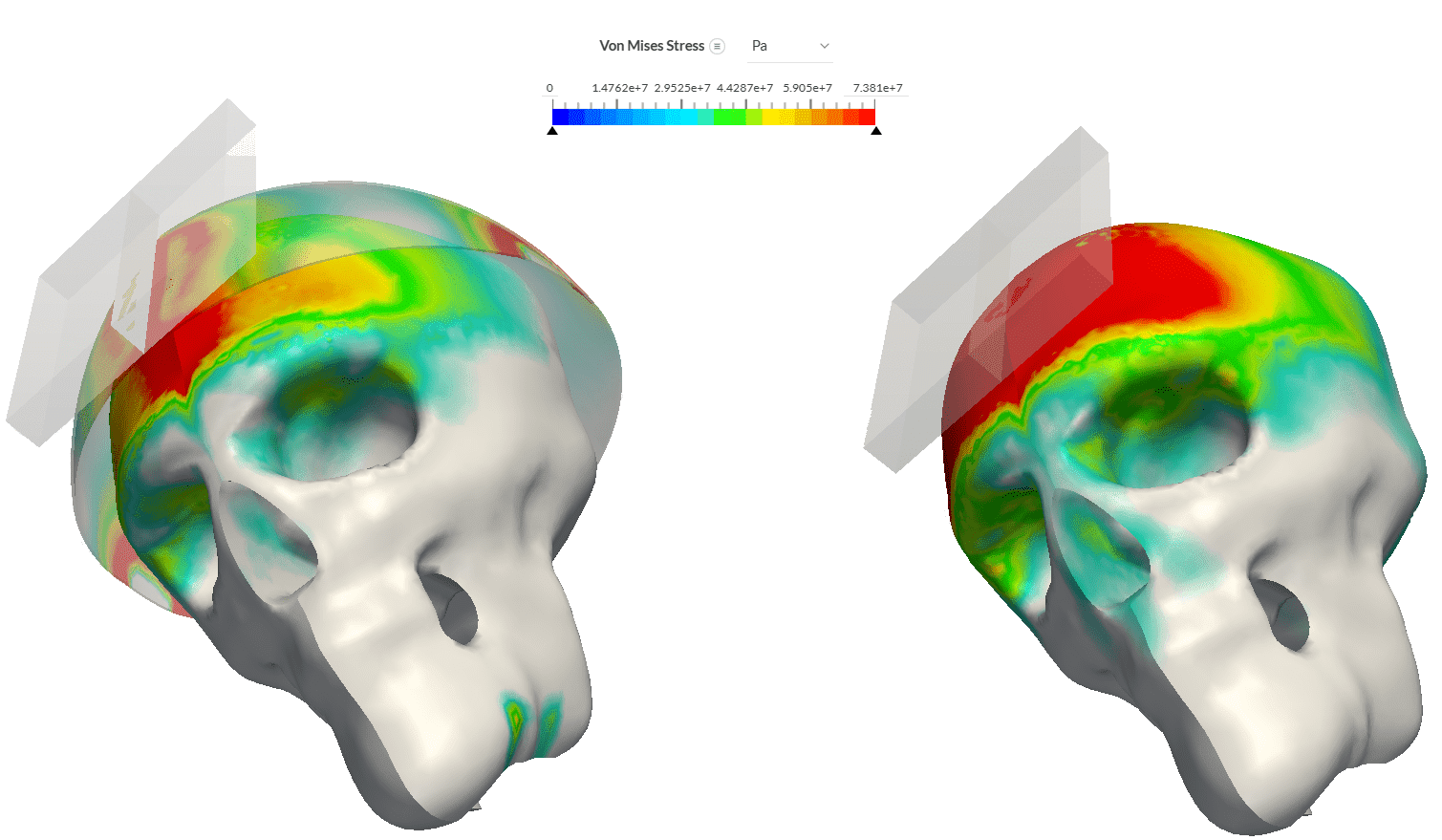
The Dynamic analysis type allows the time-dependent calculation of displacements as well as stresses and strains in one or multiple solid bodies. In contrast to static analysis, inertia effects are taken into account. Additionally, the time steps performed represent real time. The solver used to perform dynamic analysis in SimScale is Code_Aster.
In the post-processor, it is possible to analyze single time steps as well as the dynamic performance as a function of time. Similar to a static analysis, you can check for undesired deformations, or critical stresses and modify your design based on those learnings.
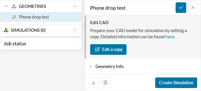
To create a dynamic analysis, the first step is to click on the desired geometry and then on ‘create simulation‘:
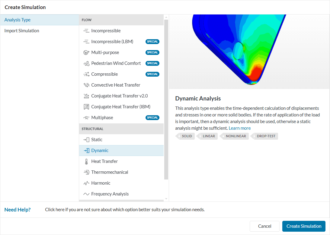
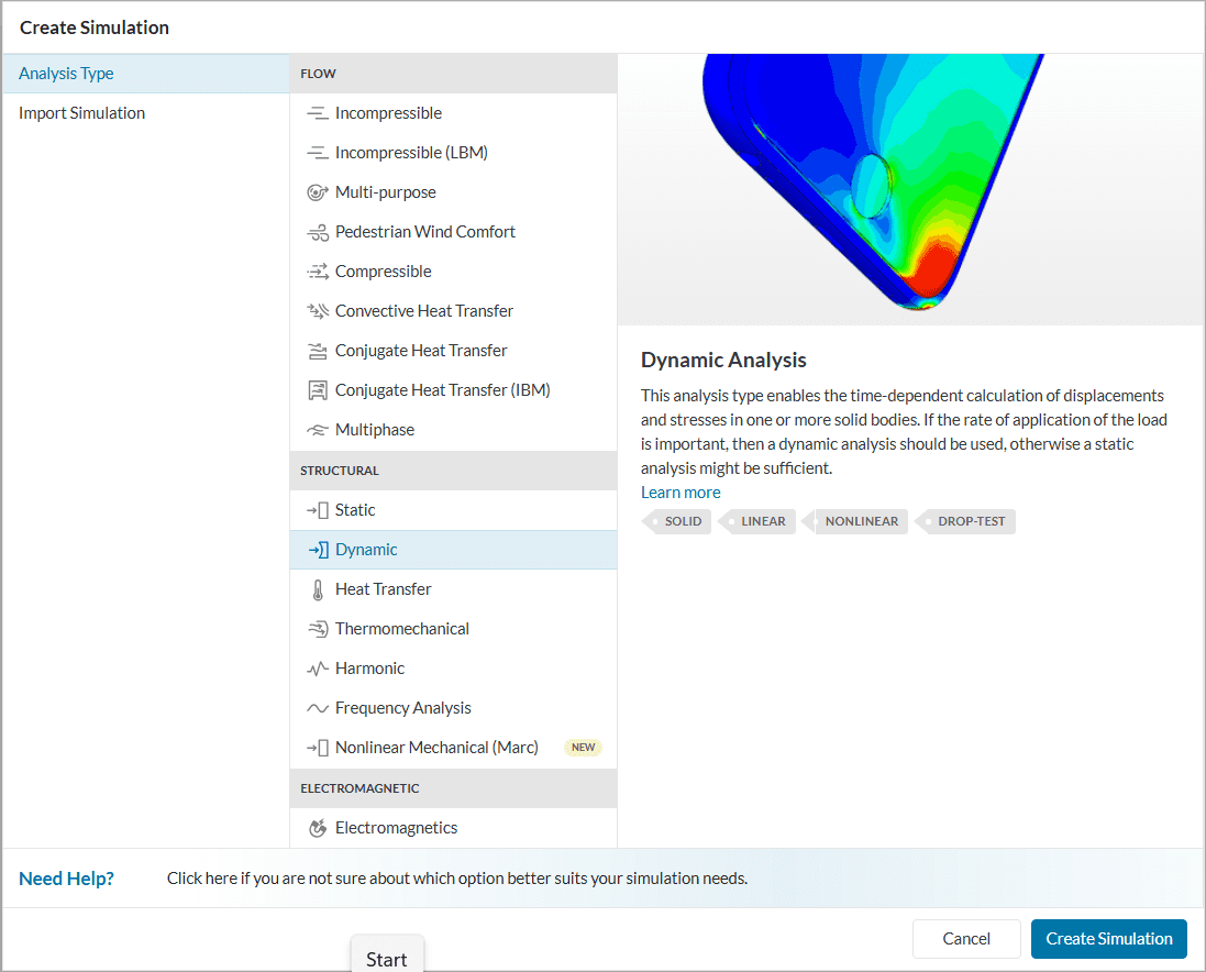
Afterward, a window with several analysis types appears. Choose the desired type from the list.
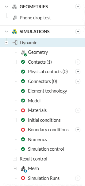
In the following, the different simulation settings you have to define are described. You will also find links to relevant documentation.
The geometry tab contains the CAD model used for the simulation. Details of CAD handling are described in the pre-processing section. For more information on the CAD upload process and the subsequent steps please read our standard documentation.
If you have an assembly of multiple bodies that are not fused together. All contacts in the system are automatically detected when a geometry is selected for a dynamic analysis. By default, they are set to bonded. Sliding contact and cyclic symmetry are also available. For more information about contacts check this page.
In the physical contacts tab, you can define contact pairs of faces or face sets. The distance between these faces is monitored during the simulation. If they touch each other, the interaction forces that prevent those faces from interpenetrating are taken into account.
The solution methods for physical contacts are available below:
Element technology refers to the numerical formulation for the solid finite element used in the simulation. This includes the mesh order, reduced integration, and mass lumping.
In the Model section, one can define a gravitational load for the whole domain. Additionally, you can determine the geometric behavior of the model.
To define the material properties of the domain, make sure to assign exactly one material to every part. Furthermore, you can choose the material behavior describing the constitutive law that is used for the stress-strain relation and the density of the material.
Please note that the density is used for volumetric loads, such as gravitation. For dynamic simulations, inertia effects are also taken into account. Please see the materials section for more details.
For a time-dependent behavior of a solid structure, it is important to define the initial conditions carefully, since these values determine the solution of the analysis. In a dynamic analysis, the displacement, velocity, and acceleration are the time-dependent variables. They define the initial state of the domain before the loads and constraints are applied.
Per default, the displacements, velocities, and accelerations are initialized as zero magnitude vector. Thus, if you use the default values, there will be no displacement and velocity in the initial state.
Additionally, an initial stress state can be defined, as it is a nonlinear analysis type. If not changed by the user, the stresses are also taken as zero initially.
In a dynamic analysis, users can define constraints and loads via boundary conditions.
If you want to determine the position of a part of the domain, add at least one displacement constraint in every coordinate direction. Otherwise, the part is allowed to move freely in space. Free motion can be intended in some cases, for example, drop tests.
In case of missing force boundary conditions, including gravitation, the geometry becomes load-free, and, apart from the prescribed displacement boundary conditions (constraints), no deformation will evolve. This might be intended to determine the strain distribution, for example, in pre-clamped structural components.
For an overview of the boundary conditions available, please check this page.
Under numerics, you can set the equation solver of your simulation. The choice highly influences the computational time and the required memory size of the simulation. For a dynamic analysis, you can also define the time integration scheme at this point. This page gives an overview of the solvers.
The simulation control settings define the overall process of the calculation. In there, users can set, for example, the simulation interval, minimum/maximum time step lengths, and the maximum runtime for the simulation.
Under result control, users can specify additional parameters of interest to be calculated. Monitors can also be defined. For example, one can set area and volume average controls, as well as point data for monitoring quantities on specific points.
For more information about result controls, check this page.
Meshing is the discretization of the simulation domain. It essentially means to split up one large problem into multiple smaller mathematical problems.
For a dynamic analysis, the standard algorithm is available. For more information about meshes, make sure to check the dedicated page.
Last updated: July 17th, 2025
We appreciate and value your feedback.
Sign up for SimScale
and start simulating now