In Pedestrian Wind Comfort (PWC) analyses, the main target is to generate wind comfort results at the pedestrian level. This article explains if the surface roughness will affect the PWC results and, if yes, then how.
1. Wind Exposures
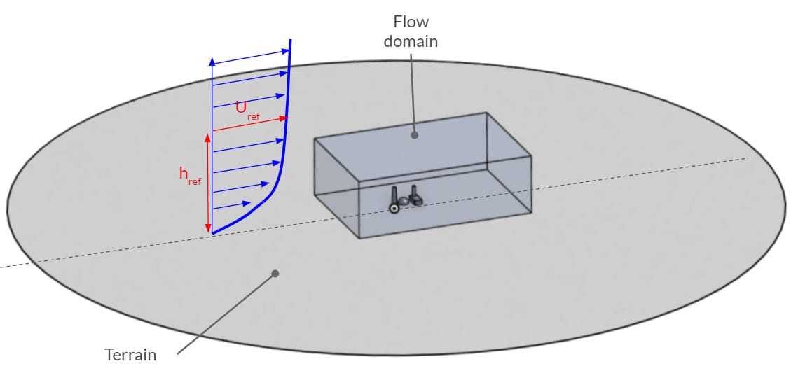
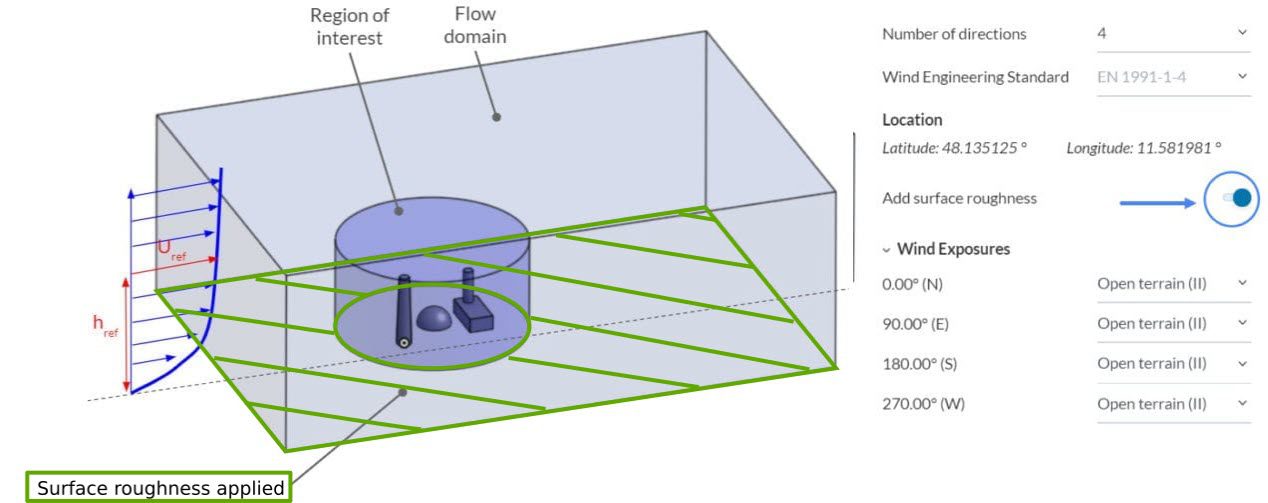
In PWC analysis, we simulate the effect of wind over the model with respect to multiple wind directions simultaneously. In reality, wind speed varies with respect to height. This is called the Atmospheric Boundary Layer (or ABL). ABL depends on the height of the obstacles (buildings, trees, terrain, etc.).
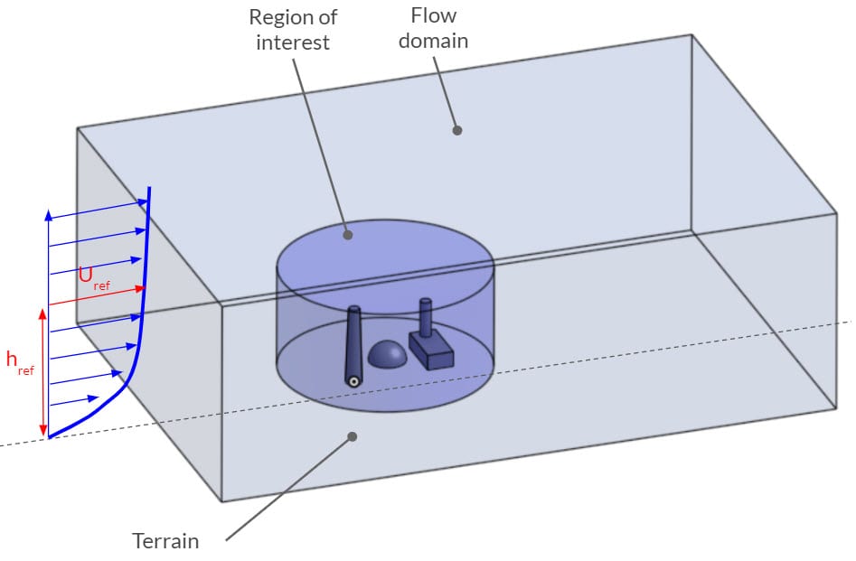
In order to reduce the computational expense, we model only a sufficient portion of the geometry. In other words, we simplify the model by removing obstacles outside of the flow domain. After that, we define a wind exposure category for each wind direction, with respect to the unmodeled region.
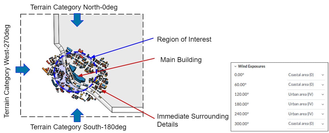
It is important to keep in mind that exposure only affects the ABL profile, not the physical terrain roughness! In other words, by defining the wind exposure categories, we modify the ABL inlet profile in each wind direction.
For more information about the wind exposure categories, please visit this documentation.
2. Roughness
Wind exposure categories only modify the incoming wind profiles to the domain, which is good enough for most cases. If you have cleaned the buildings outside of the region of interest (ROI) or cleaned some small obstacles, such as trees, you might need to add roughness.
2.1 Add Surface Roughness in Wind Conditions
If your model does not include the terrain, it will be assumed as plain ground. This means that the bottom of the flow domain will be the ground level. In this case, you can activate the Add surface roughness option to add roughness effects on the ground. Roughness value will be taken as a ground surface value outside the region of interest and will be automatically added with respect to the corresponding wind direction.
2.2 Surface Roughness Under Advanced Modelling
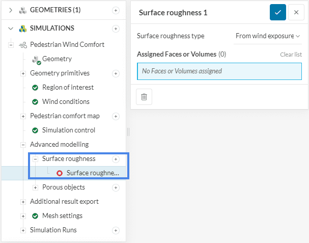
If your model includes the terrain (uneven ground), then the surface roughness setting under the Wind conditions will not capture the effects of the surface roughness. If these should be captured, one can add the surface roughness under the ‘Advanced modelling‘ tab. The surface roughness value can be defined using three different surface roughness types.
To assign a surface roughness type to a surface, click on the plus icon next to Surface roughness and select the Surface roughness type and the surface, for which a custom surface roughness should be defined.
Best Practices
Here are the methods that we recommend regarding this topic:
- Examine the region you are simulating and assign realistic wind exposure categories.
- Model the buildings not only inside the ROI, but also inside the flow domain.
- Use porous media – Tree feature to add vegetation.
- Create the CAD model with separate surfaces to assign multiple roughness values.
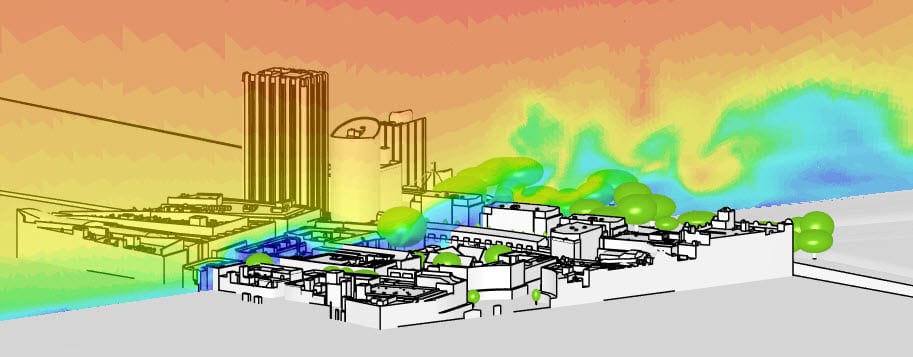
The following picture compares pedestrian wind comfort analysis results of Bristol City based on two scenarios. On the left, no additional surface roughness is applied, meanwhile, the picture on the right has individual roughness values applied to the different terrain types such as roads, green fields, and other man-made structures.
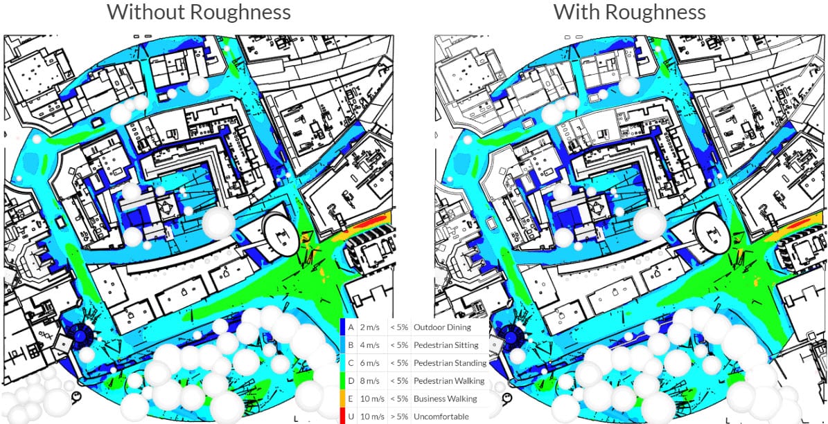
We can see that the addition of surface roughness slightly affects the results because there are areas where the category changes to a more comfortable ca
Note
If none of the above suggestions solved your problem, then please post the issue on our forum or contact us.
References