Validation Case: Elastoplastic Notched Plate
This validation case belongs to solid mechanics. It aims to validate the following parameters:
- Plastic material behavior
- Reduced integration element type
The simulation results of SimScale were compared to the reference values presented in [SSNP123]\(^1\).
Geometry
Find below the notched plate geometry used for this validation case:
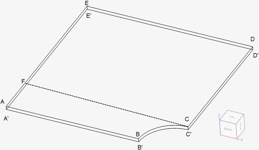
The plate dimensions are tabulated below:
| A | B | C | D | E | F | |
| x | 0 | 0.004 | 0.005 | 0.005 | 0 | 0 |
| y | 0 | 0 | 0.001 | 0.005 | 0.005 | 0.001 |
| z | 0.0001 | 0.0001 | 0.0001 | 0.0001 | 0.0001 | 0.0001 |
The corresponding nodes marked with an apostrophe (‘) are translated 0.0001 \(m\) along the negative z-direction.
Analysis Type and Mesh
Tool Type: Code_Aster
Analysis Type: Nonlinear static
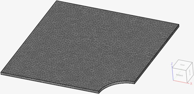
Mesh and Element Types: The meshes used in this project were created in SimScale with the standard algorithm.
| Case | Element Type | Number of Nodes | Element Technology |
| (A) | 2nd Order Tetrahedral | 44211 | Standard |
| (B) | 2nd Order Tetrahedral | 44211 | Reduced integration |
Find below the mesh used for cases A and B. It’s a standard mesh with second-order tetrahedral cells.
Simulation Setup
Material:
- Steel (plastic behavior)
- \(E\) = 200 \(GPa\), \(v\) = 0.3
- \(\rho\) = 7870 \(kg/m^3\)
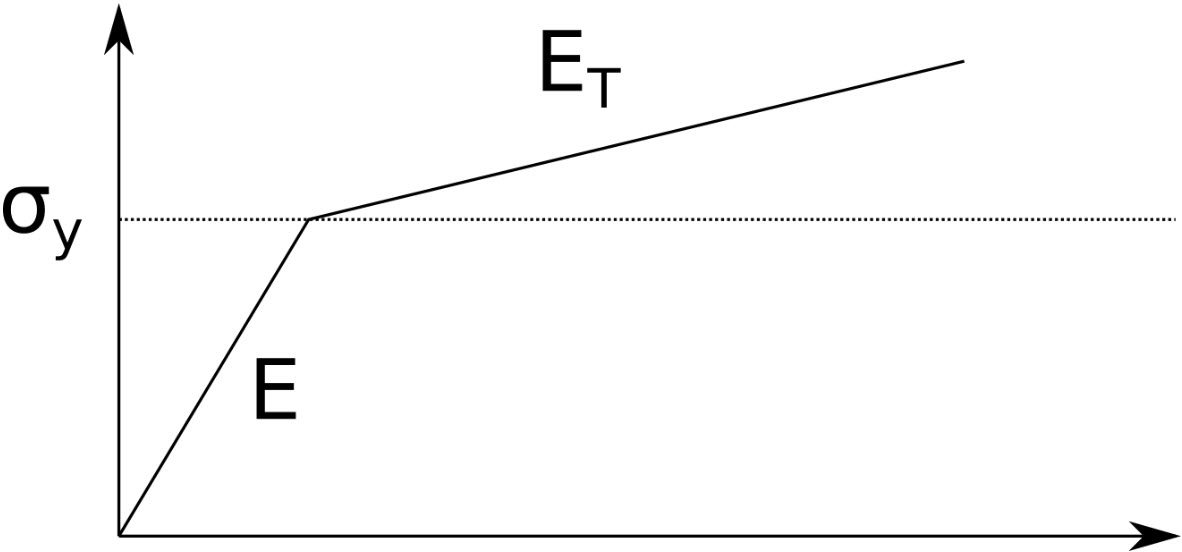
- \(\sigma_y\) = 200 \(MPa\), \(E_T\) = 1000 \(MPa\), as shown below:
Boundary Conditions:
- Constraints
- \(d_x\) = 0 on face AA’E’EF
- \(d_y\) = 0 on face AA’B’B
- \(d_z\) = 0 for all nodes
- Face EE’D’D: displacement of 0.0001 \(m\) in the positive y-direction
Result Comparison
The results obtained from SimScale for the Cauchy stress \(\sigma_{yy}\) along the FC line are compared to the values of reference from [SSNP123]\(^1\). These values of reference were extracted with WebPlotDigitizer. Figure 5 shows the results for case A, where element technology is set to standard:

Similarly, for case B, where reduced integration was used:
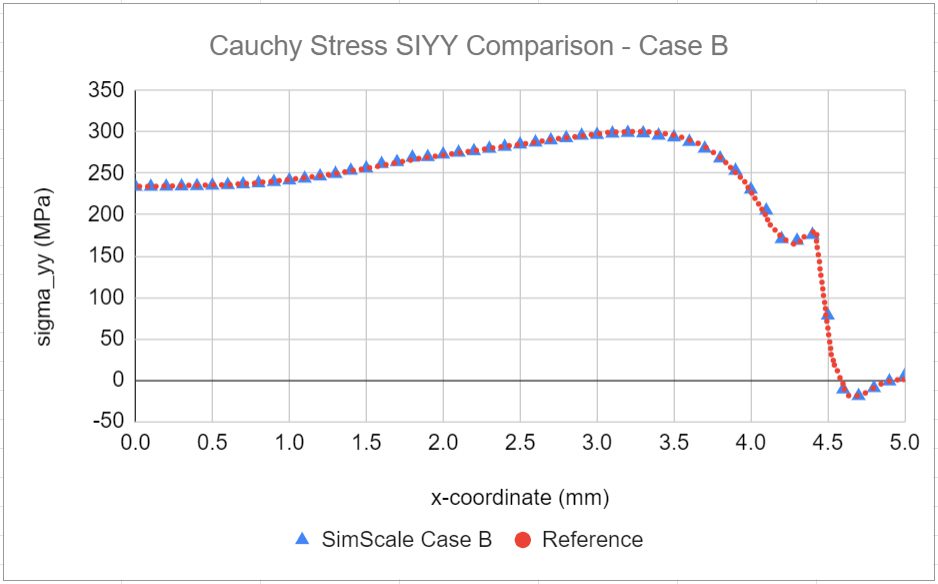
In both Figures 5 and 6, SimScale’s results show good agreement with the reference values.
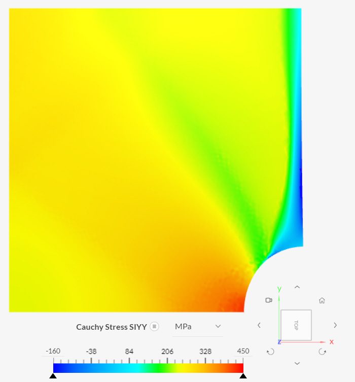
Inspecting the Cauchy stress \(\sigma_{yy}\) for case B in the post-processor:
Last updated: November 7th, 2023
Did this article solve your issue?
How can we do better?
We appreciate and value your feedback.


