Documentation
In structural analysis (except for heat transfer), the fixed value boundary condition sets a fixed displacement on the assigned face or volume. The user can use this boundary condition to restrict a movement in only one or two directions. Furthermore, the value of the displacement can be a function of coordinates or time added using the table or through a formula.
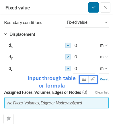
Any value entered basically means the allowed displacement of that face/volume in that particular direction. The value entered can be negative as well and signifies the allowed displacement in the opposite direction. As mentioned before, the displacement can also be defined with a table or a formula. Usually, this is used when the displacement varies over time or as a function of the length of the model.
The user can allow an unconstrained movement by clicking the checkbox ![]() (and toggling it off) in the direction where movement is necessary. For example, a pure movement in the vertical direction will need complete restriction in the horizontal axes.
(and toggling it off) in the direction where movement is necessary. For example, a pure movement in the vertical direction will need complete restriction in the horizontal axes.
The picture below is a slice of an annulus that is subjected to volume load.
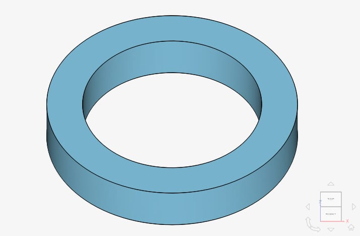
However, since the movement of the annulus will only be in the x- and y-axes the displacement needs to be fixed in the z-direction to zero. Hence, the fixed value boundary condition will be necessary in this case.
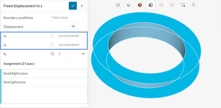
This boundary condition is applied to the top and bottom face of the annulus and the movement is restricted to the x- and y-axes. This is why the displacement in the x and y-axes is unconstrained while the displacement in the z-axis is fixed at 0 \(m\). The deformation in each direction can be seen in the figure below.
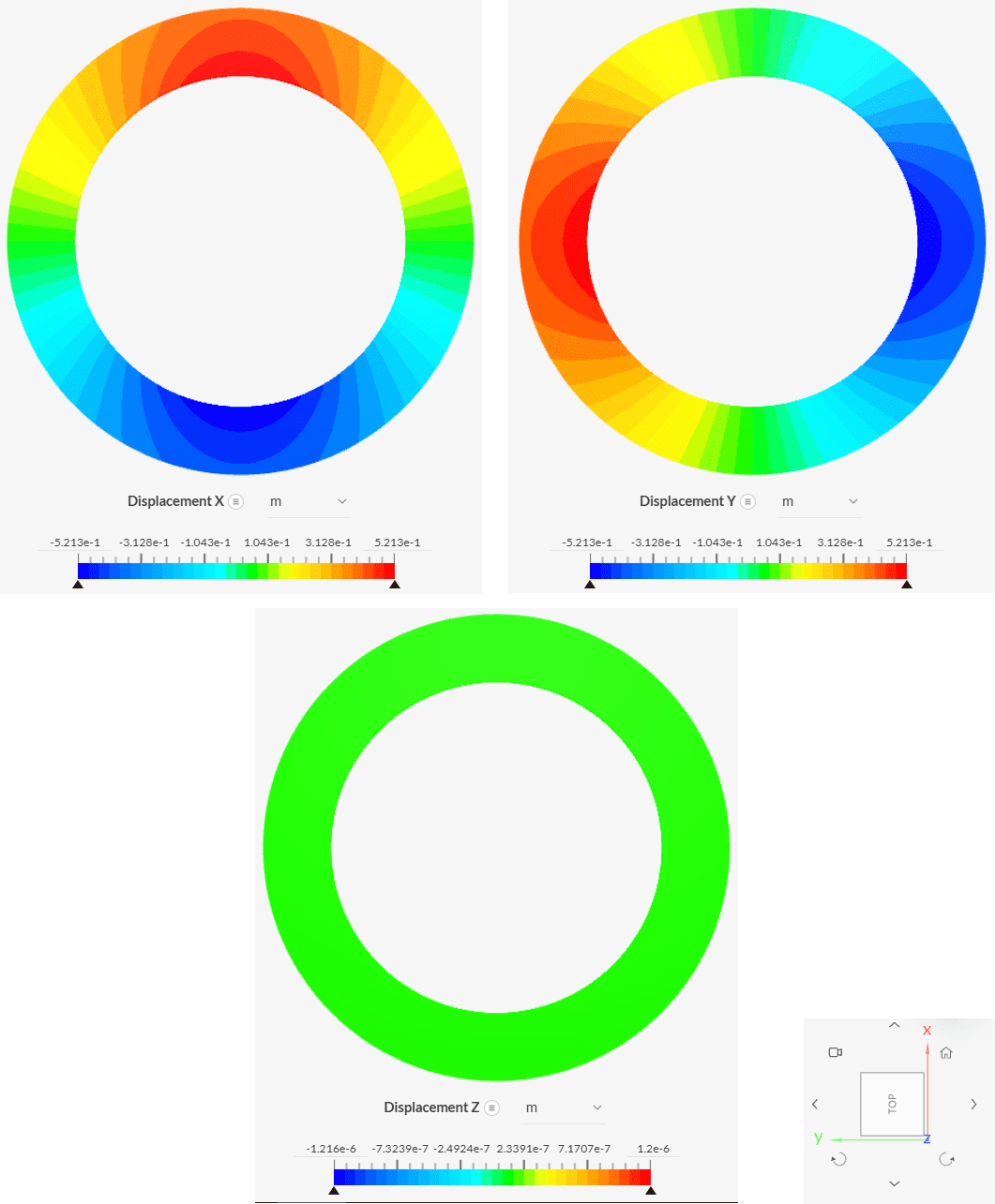
The picture above shows that the deformation in the z-axis is insignificant when comparing it to the deformation in the x- and y-direction.
Note
If the user wants to restrict all movement, then the fixed support boundary condition is recommended.
Last updated: December 25th, 2024
We appreciate and value your feedback.
Sign up for SimScale
and start simulating now