This article explains why Standard mesher does not take into consideration the defined mesh size and makes the mesh coarser.
Before we start, we advise you to visit the documentation page on CAD preparation and upload. In addition, please visit the following Tutorial to learn how to use the standard mesher.
What Happened?
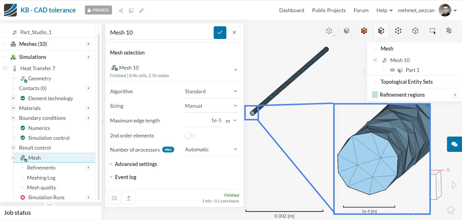
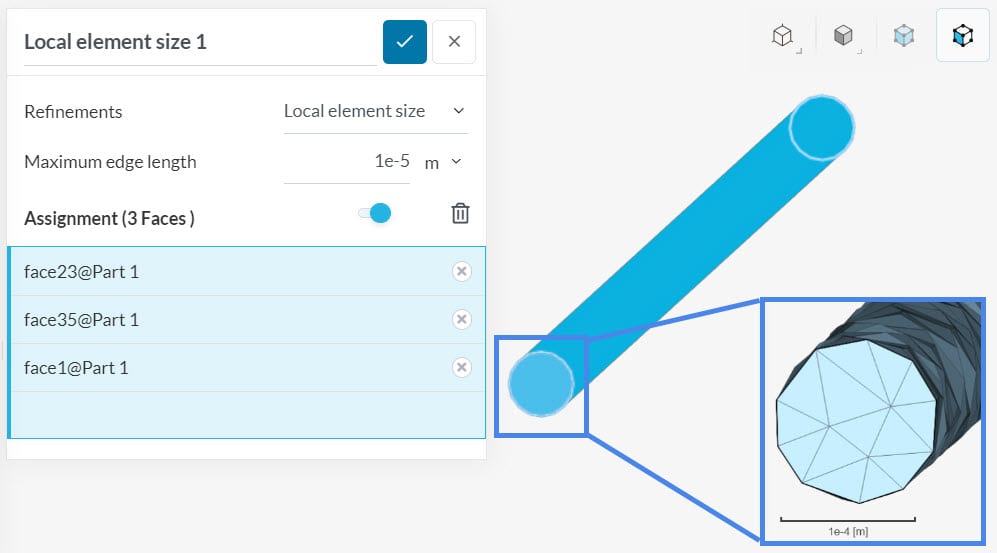
- The user defined the maximum element size (maximum edge length). However, the Standard mesher generated coarser mesh elements, which have a much higher size than what was defined.
- The user defined the boundary layer (BL) size. However, the mesher generated thicker BL.
- The user defined the boundary layer (BL) size. However, the mesher did not generate any BL.
What Could Be the Possible Reason?
This issue happens when a CAD model tolerance is too high:
The model tolerance is something that all CAD kernels need because floating-point arithmetic inside a computer is inexact. Simply speaking, the tolerance of a vertex can be imagined as a bubble around the vertex with a given radius. Any other vertex that is inside the bubble will be logically merged with this one and they appear as one. This is used to close a model up, even if the numbers inside aren’t exactly equal.
The model tolerances are adjusted by the kernel during model operations. Typically, the more inexact the modeling is, the larger the tolerances get reducing the model quality.
The problem that arises during meshing is that model tolerance is a limiting factor to the mesh size. We cannot make the mesh smaller than the model tolerance, and for practical reasons, we need to keep a safety margin of about 10 x the tolerance. This means that a CAD model with very high tolerances cannot produce a fine mesh. It’s impossible.
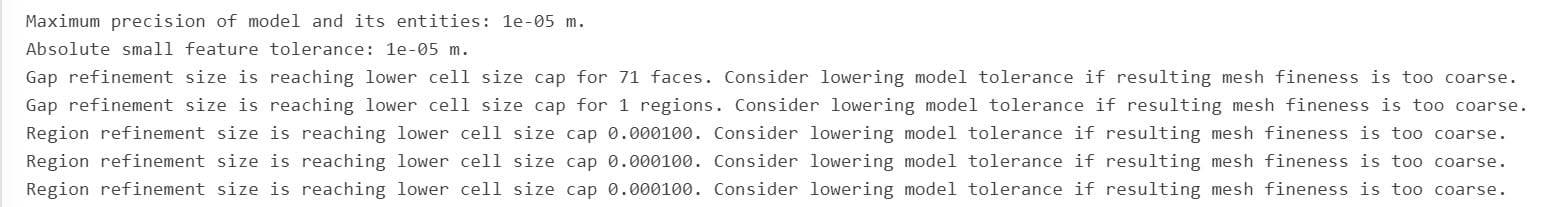
This error message may appear in the meshing log:
What Can I Do Now?
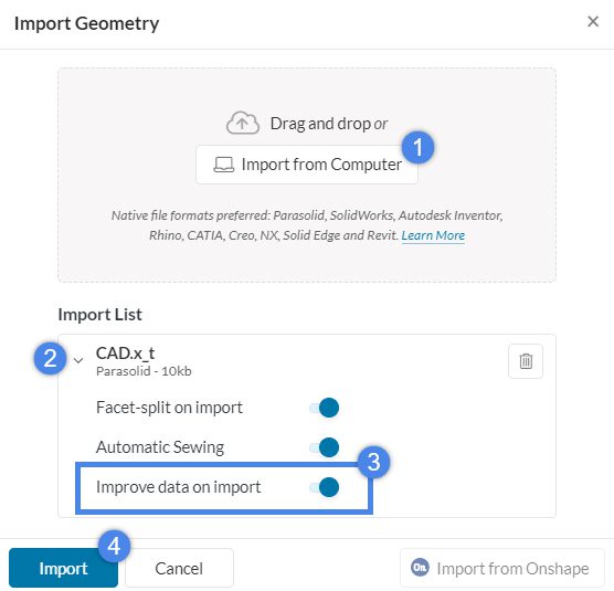
When “Improve data on import” is active during the CAD upload, we reduce the tolerances to the minimum possible, meaning the smallest bubble around each vertex without changing the model topology. This makes it possible to create a finer mesh and often provides a viable solution. However, the CAD upload can take a considerable amount of time when this option is used in very complex models. Therefore you may opt-out and reconsider in case you face issues in geometry handling or meshing.
This feature is active as default in the CAD upload process, therefore the majority of these problems should have already been solved automatically. If this doesn’t help, some CAD tools also provide solutions. Check your CAD tools optimization functionality. Many CAD tools have “optimize edges” or similar features to optimize model tolerance.
Important Information
If none of the above suggestions solved your problem, then please post the issue on our forum or contact us.


