Tutorial: Creating a Standard Mesh on the Example of a Heat Sink
This tutorial demonstrates how to create meshes using the Standard mesh tool. To showcase the effect of the setup parameters, a total of 6 meshes will be created, using a heat sink as the model.
Overview
This meshing tutorial teaches users how to:
- Create meshes using the standard meshing algorithm;
- Apply different types of mesh refinement;
- Use all basic and advanced settings;
- Inspect the mesh.
Note
The usual workflow in SimScale is the following:
- Prepare the CAD model for the simulation;
- Set up the simulation;
- Create the mesh;
- Run the simulation and analyze the results.
Since this is a meshing tutorial, it will focus on the third step.
1. Prepare the CAD Model and Select the Analysis Type
First of all, click the button below. It will copy the tutorial project containing the geometry into your workbench.
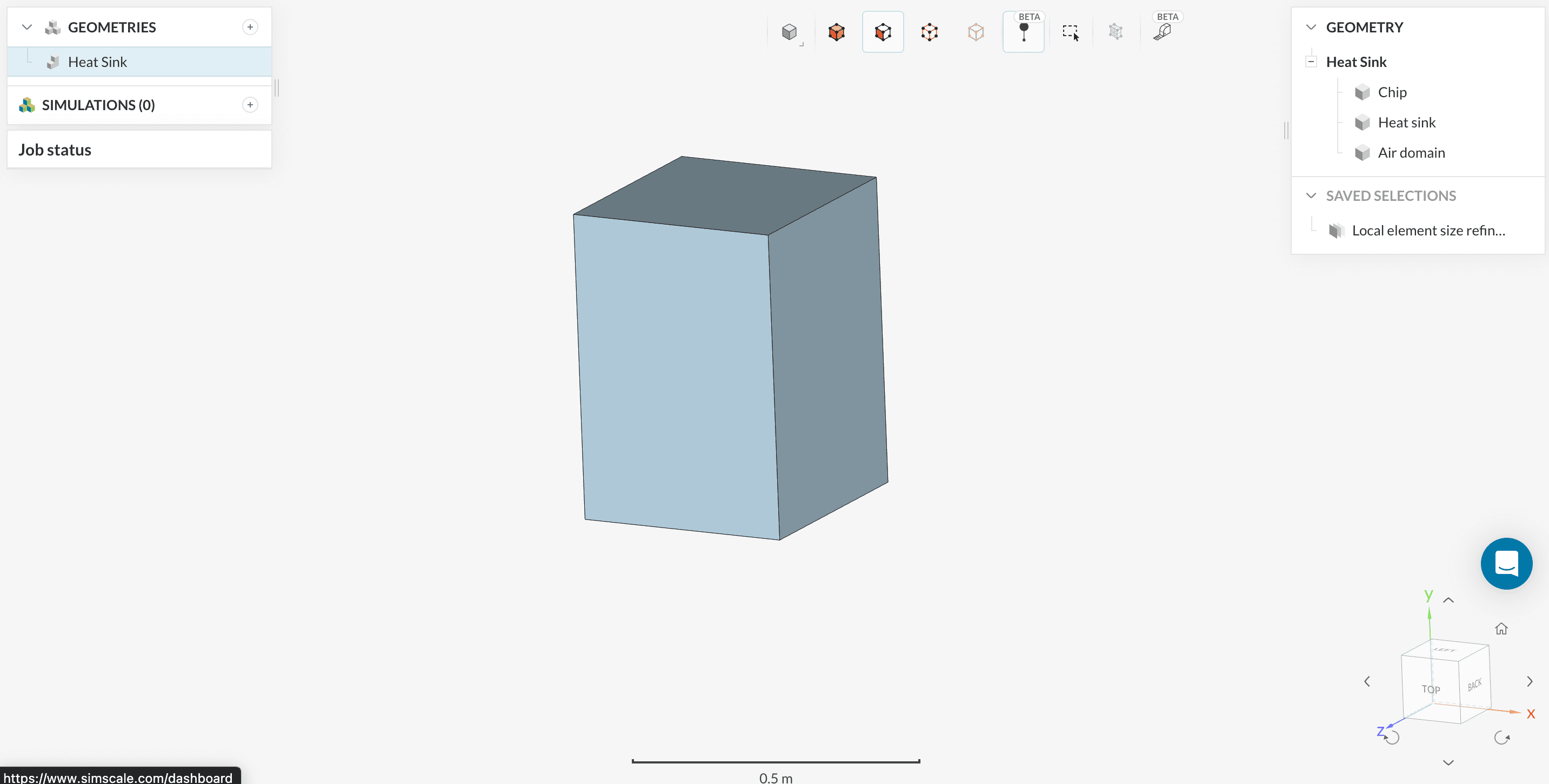
The starting project contains a heat sink, a chip, and the flow region. The following picture demonstrates what should be visible after importing the project.
1.1 Create the Simulation
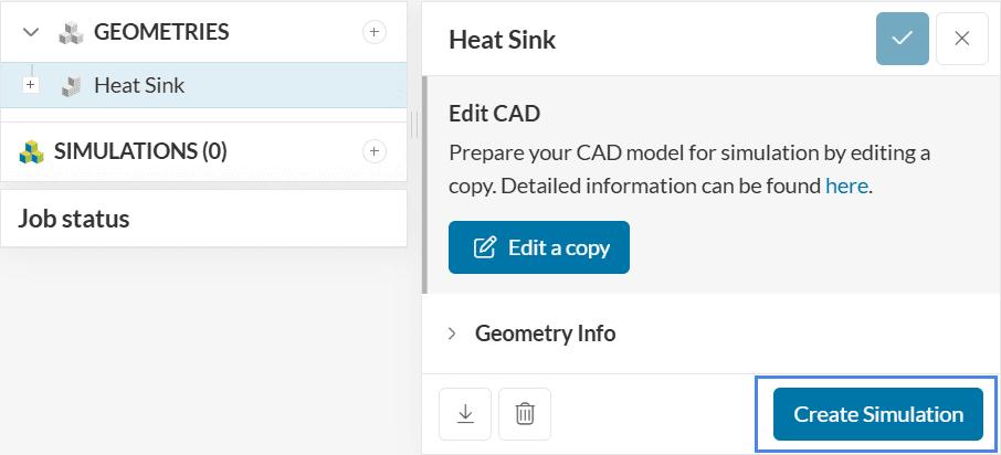
Since we have a flow region and solid parts in the geometry, there will be interfaces between these volumes. In these cases, to enhance the detection of contacts, it’s recommended to run an imprint operation.
In this tutorial, the Imprint operation has already been performed. Therefore, we can directly proceed to ‘Create the Simulation’:
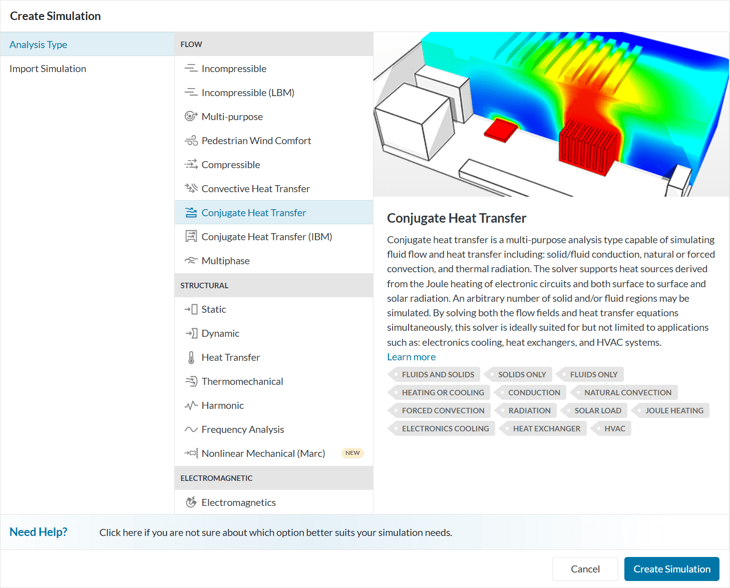
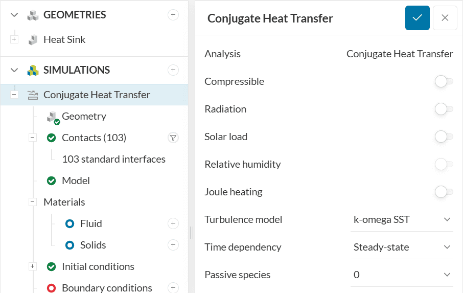
Now, the analysis type widget opens. From the list, select ‘Conjugate Heat Transfer’, and click once more on ‘Create Simulation’:
After creating a simulation, the simulation tree loads in the left-hand side panel. The global simulation settings will remain as default.
2. Simulation Setup
Important
In section 2 of the tutorial, we set up a simple simulation to make use of the physics-based meshing functionality.
If you are not interested in the physics-based meshing option, you can directly jump to section 3 Standard Mesh.
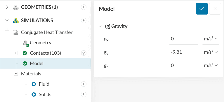
2.1 Model
Specify gravity under Model. It will be -9.81 m/s² in the y-direction:
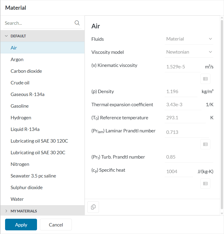
2.2 Materials
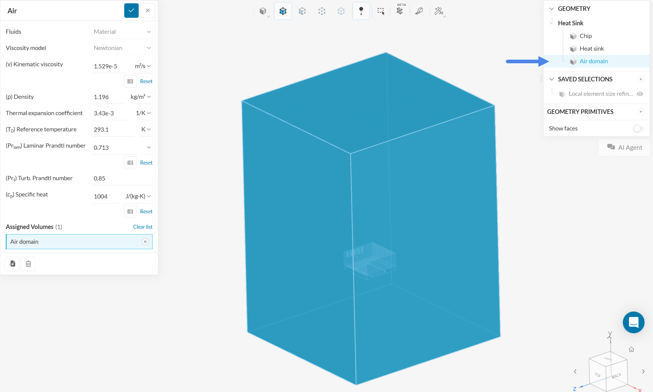
In the simulation tree, please expand the Materials tab. Click on the ‘+ button’ next to Fluids and choose ‘Air’ from the fluid materials library.
Afterward, assign it to the Air domain.
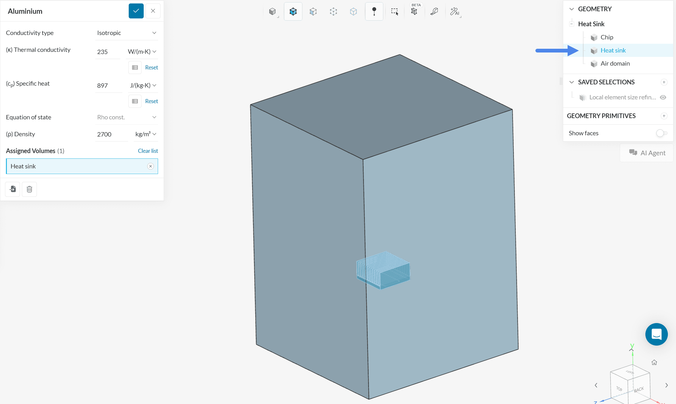
Now repeat the process for the two Solids. Assign Aluminium to the Heat sink and Silicon to the Chip:
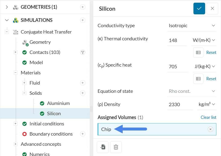
Following the same workflow for the Chip volume, the material will be Silicon:
2.3 Boundary Conditions
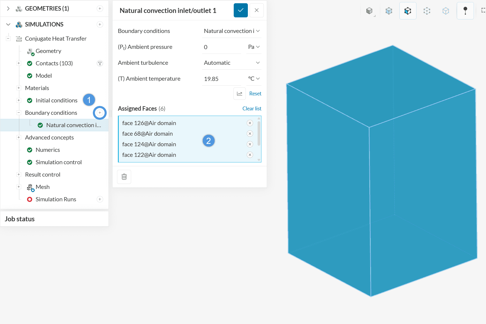
Click on the ‘+ button’ next to Boundary conditions. Select ‘Natural convection inlet/outlet‘ and assign it to the 6 outer faces of the air domain.
3. Standard Mesh
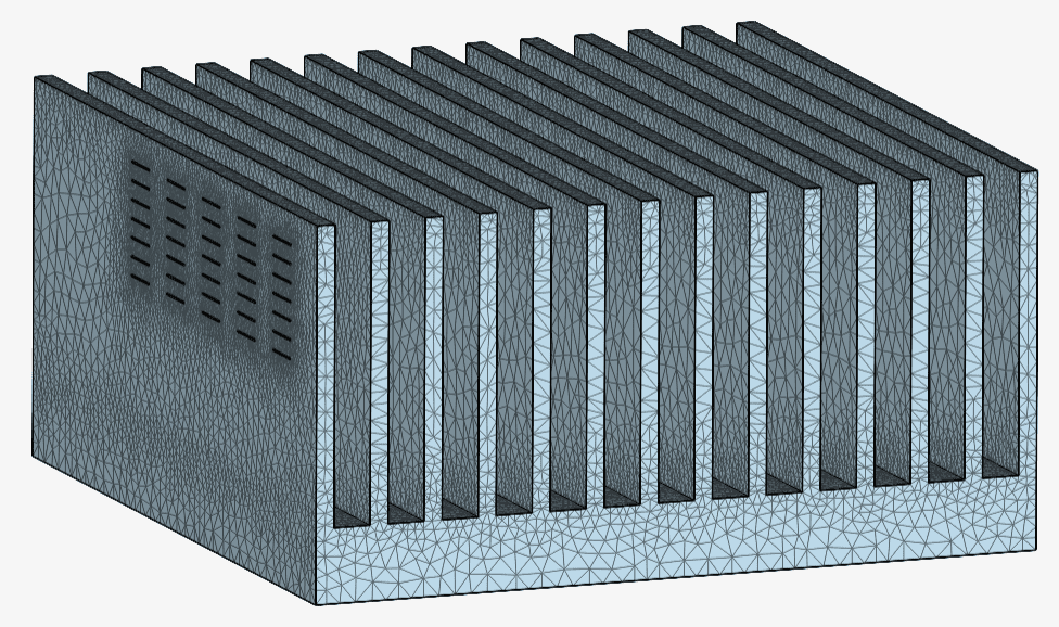
The standard meshing tool will be used to mesh the heat sink. A total of six different meshes will be created, to show how the configuration parameters affect the resulting mesh. Make sure to check this documentation page for the standard mesh settings.
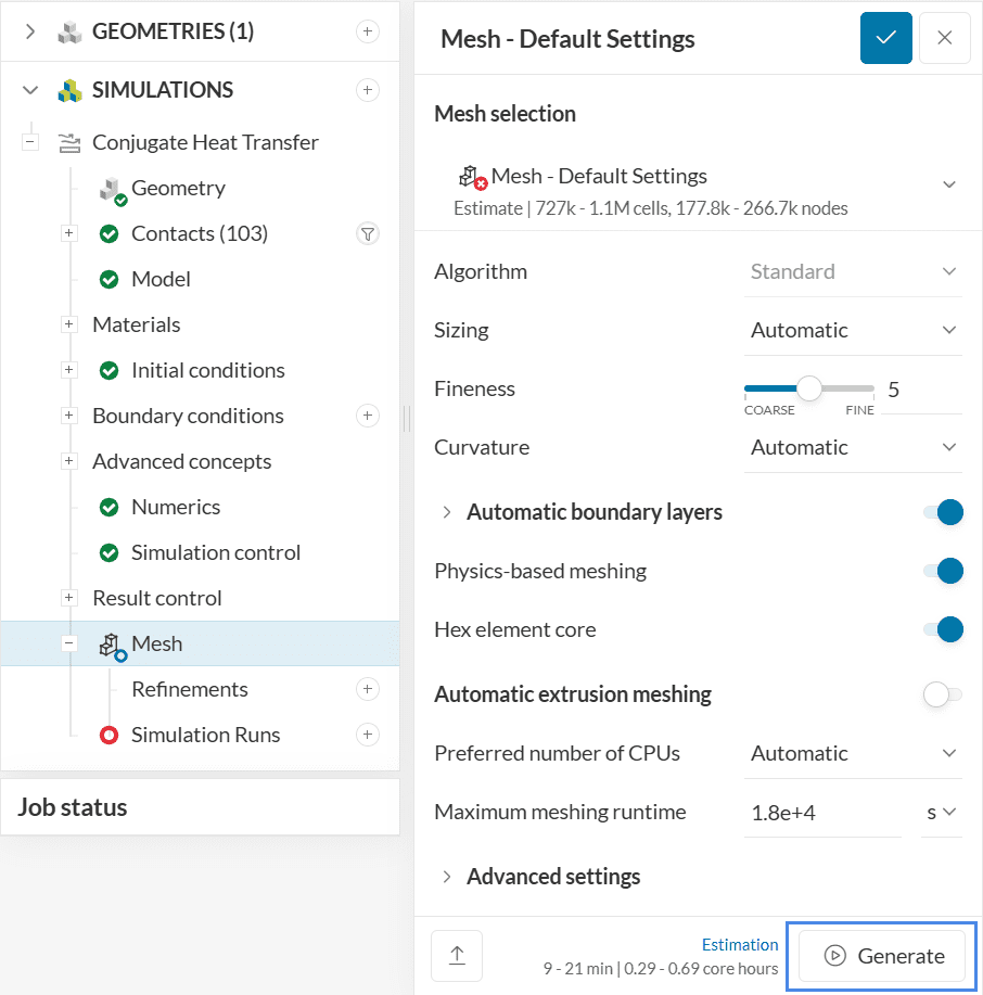
To create a mesh, please navigate to Mesh in the simulation tree. A tab with options will open.
Let’s get a brief overview of the basic settings:
- Cell Sizing can be either manual or automatic. With Manual sizing, it’s possible to specify a maximum and minimum edge lengths for cells in the entire domain;
- With the Fineness sliding bar, users can specify global levels of fineness to their meshes;
- By adjusting the Curvature definition, the user can define how many mesh cells they want to have over a 360 degree curved face, being a useful tool to automatically refine fillets and rounded faces;
- Automatic boundary layers generates layers automatically on all no-slip walls, based on the boundary conditions set by the user;
- The Automatic extrusion meshing provides extruded meshes on volumes that can be extruded, being useful to capture thin elements;
- With Physics-based meshing, the regions near inlets and outlets are automatically refined. This option is useful to capture high gradients in these regions. Furthermore, if any advanced concepts are defined (such as porous medium and power sources), the algorithm automatically assigns cell zones to these volumes. To use physics-based meshing, users have to fully set up their simulation before creating a mesh.
- When the Hex element core is enabled, the standard mesh becomes hybrid, generating tetrahedral cells close to the walls and hexahedral cells distant from walls.
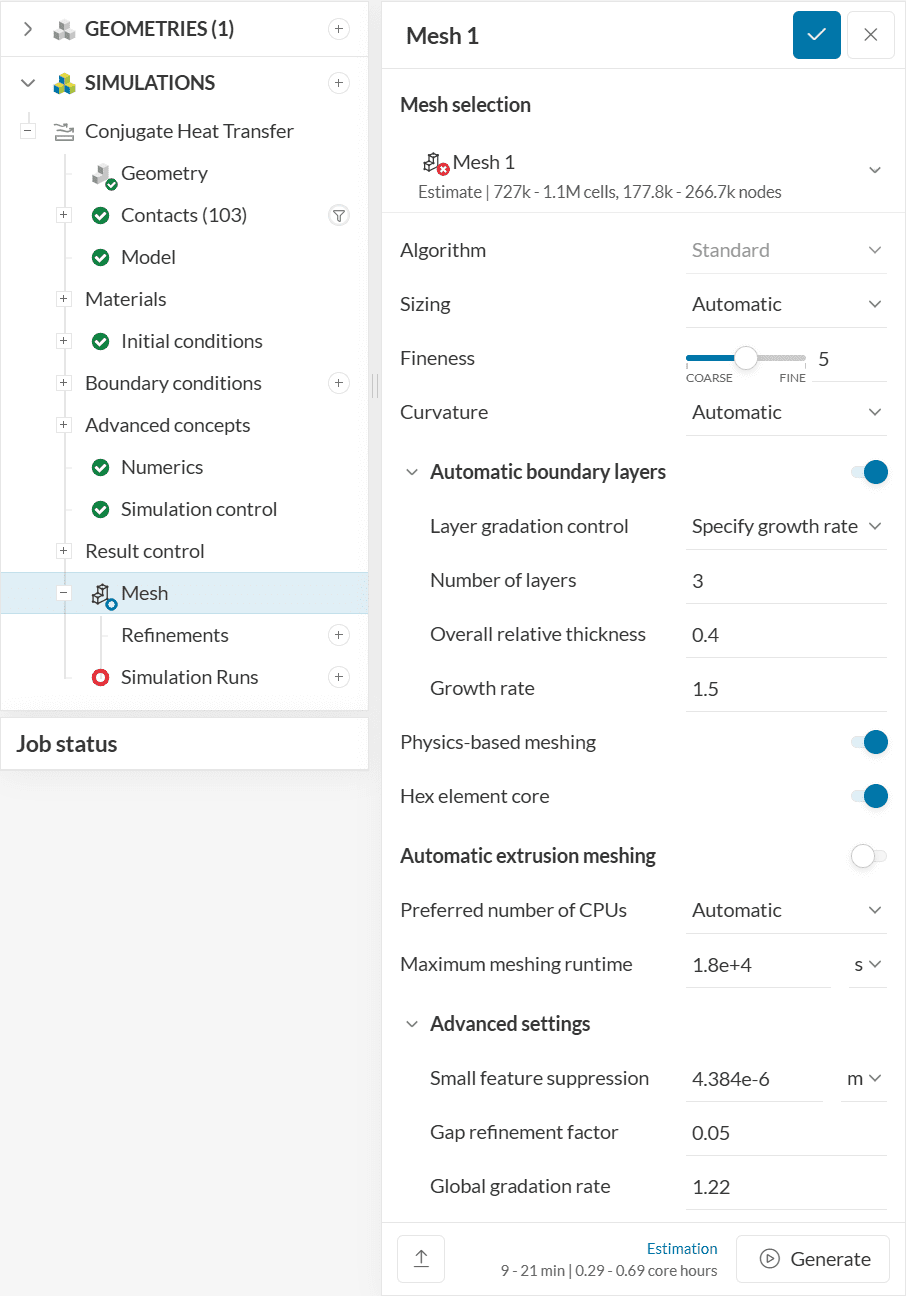
3.1 Mesh One: Default Settings
Now it’s possible to use the default settings. Please head back to Mesh and hit ‘Generate‘.
The default standard mesh takes about 5 minutes to complete. When it finishes running, you can hide the Air domain to inspect the solid parts:
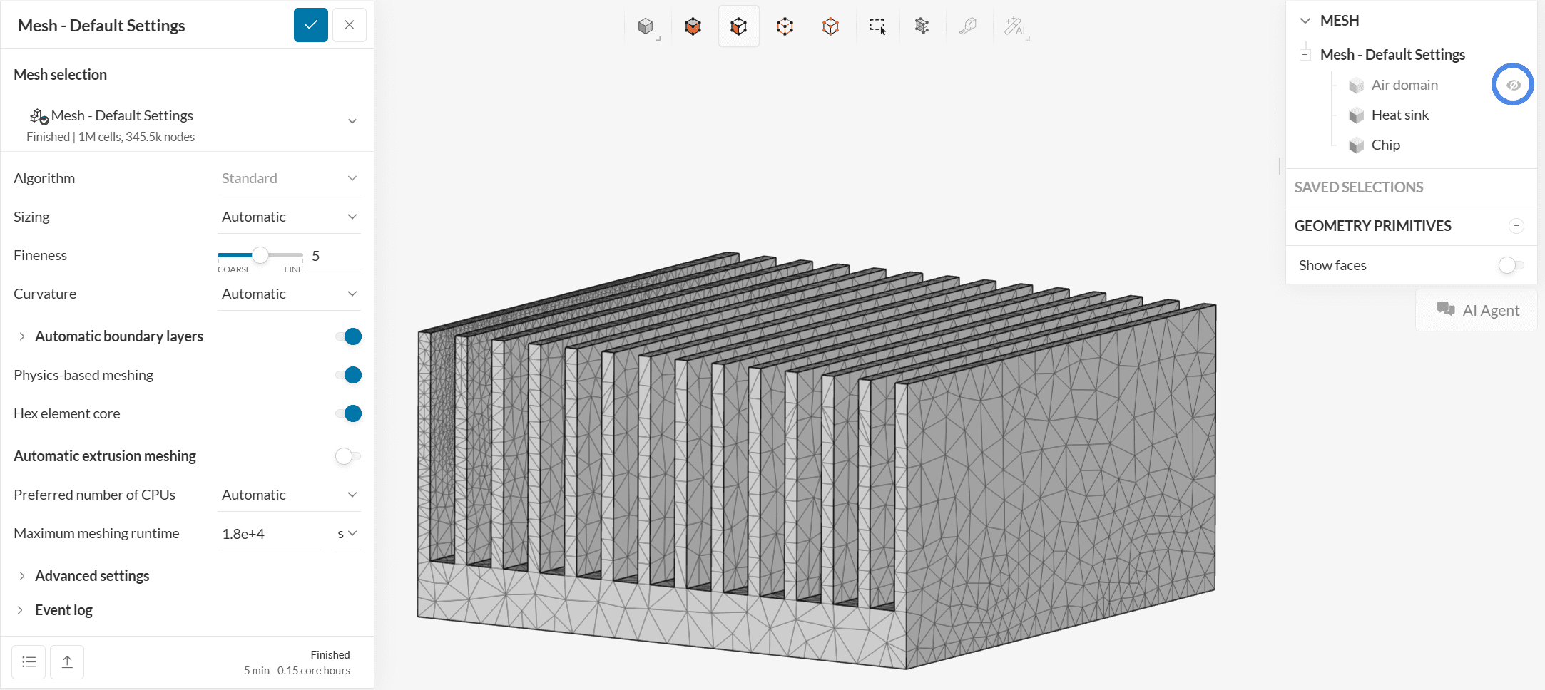
The default mesh is too coarse. For heat sinks, it’s recommended to generate a minimum of 2 or 3 elements across the fin thickness. Let’s generate a new mesh with a Fineness level of 7.
3.2 Mesh Two: Changing Global Fineness
The settings for the second mesh will be the same, except for the global level of Fineness.
Follow the steps below to create a new mesh:
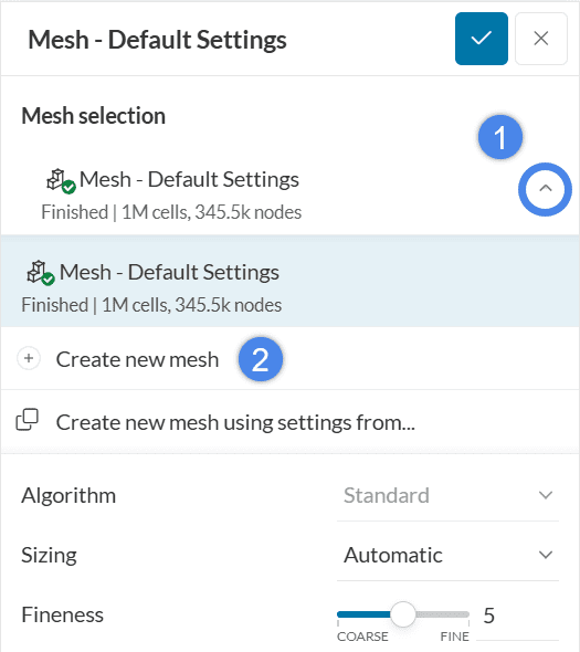
Now simply adjust the Fineness slide bar to 7 and ‘Generate’ the second mesh.
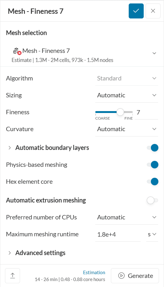
The second mesh takes roughly 10 minutes to run. Let’s now compare the heat sink discretization using the first and second meshes:
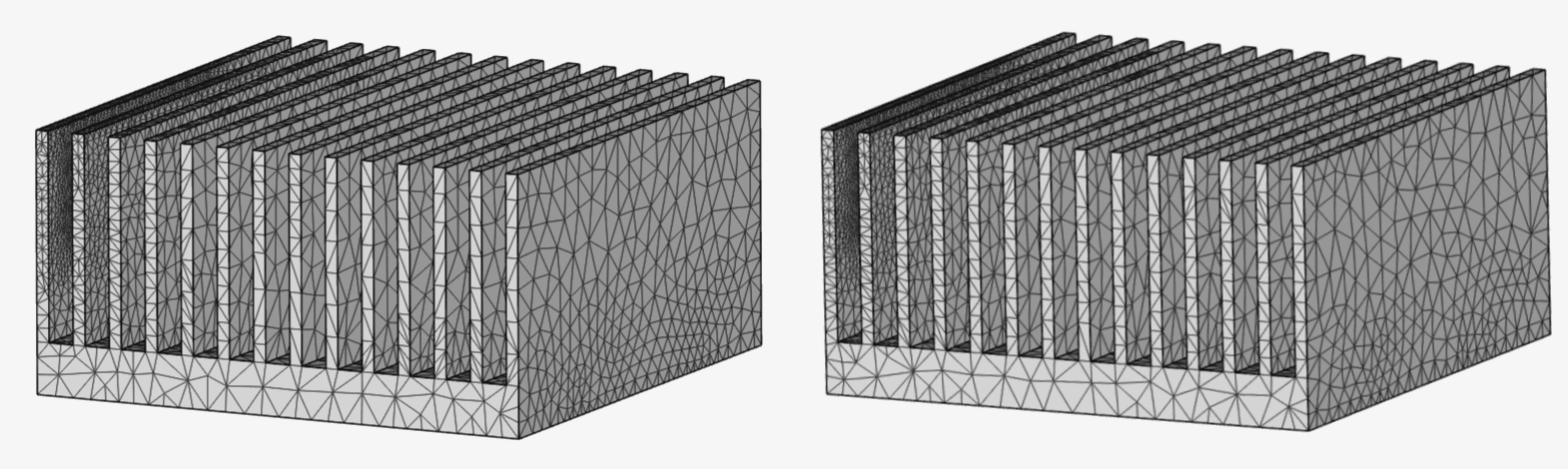
The fineness level changes the mesh size globally. Comparing the new and previous meshes, there is almost no obvious change in the element size on the heat sink. This shows that a large portion of refinement is performed in the air domain. Local refinement on heat sink and chip would be a more cost-effective way to generate a mesh.
3.3 Mesh Three: Surface Custom Sizing Refinement
Using the steps from figure 15, please create another mesh. To enhance the discretization of the fins, we will use a Surface custom sizing refinement. The other settings remain default.
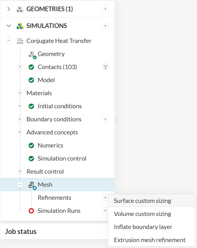
To create a refinement, click on the ‘+ button’ next to Refinements and select Surface custom sizing.
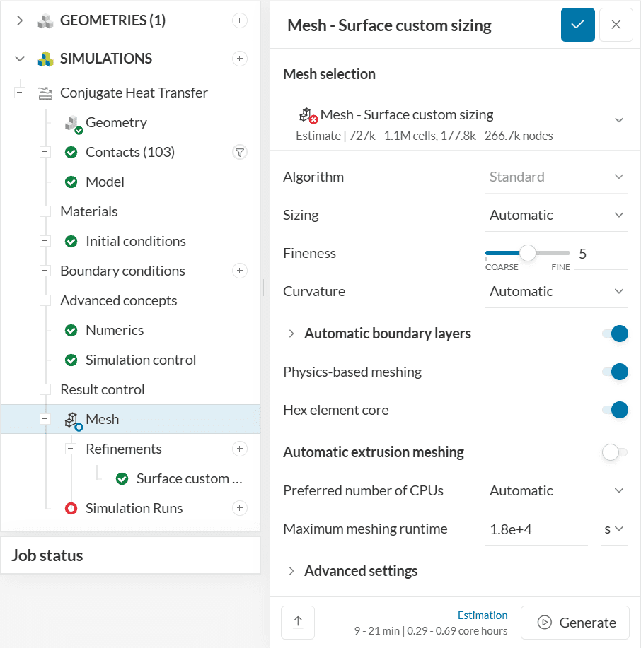
With surface custom sizing, you can specify a target element size for selected entities. It’s particularly useful to increase the resolution on small faces.
For the heat sink model, each fin is 0.002 meters thick. A Maximum/Target element size of 0.001 meters will ensure at least 2 elements across the thickness.
Set up the refinement as below using the Custom option instead of the Automatic. To save time, assign it to a pre-saved saved selection named Local element size refinement.

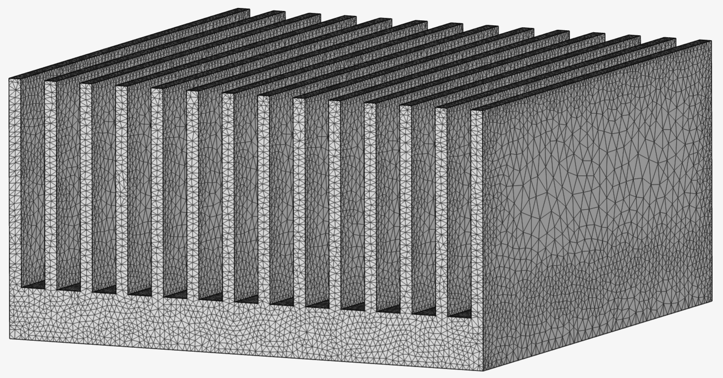
Now we can go back to the Mesh tab and hit ‘Generate’.
Now, with the controlled cell size, it’s possible to see a big difference in the fins’ discretization.
So far, we have learned how to visualize the mesh on surfaces. However, this does not give us any information regarding the interior elements. For such cases, the Mesh quality feature can be used to see the interior cells. Please follow the steps below:
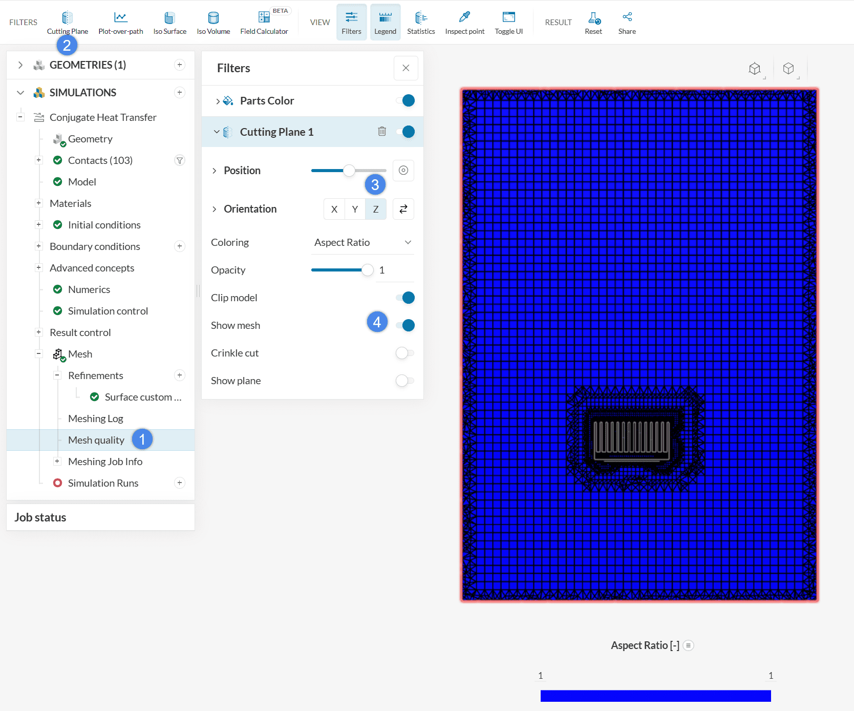
- Click on the Mesh quality
- Click on the ‘+ button’ next to Cutting Planes
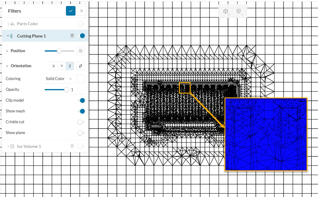
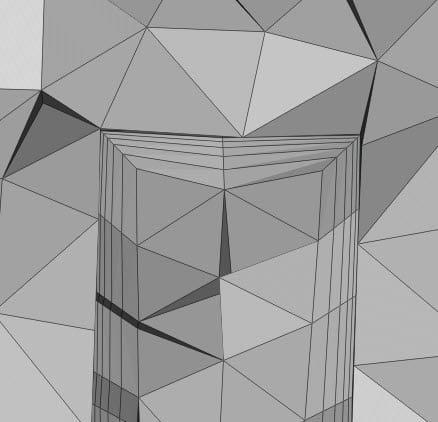
As we are not interested in seeing the quality of the cells at the moment, keep the Coloring as ‘Solid Color’ and enable Show mesh. Now the interior is visible – We can see the hexahedral cells in the middle of the domain. By zooming in to the fins, the boundary layers can be seen:
3.4 Mesh Four: Volume Custom Sizing
From the image above, we can see that mesh size suddenly increases when it transitions from tetrahedral to hexahedral cells.
Due to the natural convection, a hot air plume is expected to rise along the vertical axis of the heat sink. To ensure that we are capturing the convection plume more accurately, a region refinement is recommended.
For the fourth mesh, let’s copy the third mesh and add a volume custom sizing. To copy a mesh, follow the steps below:
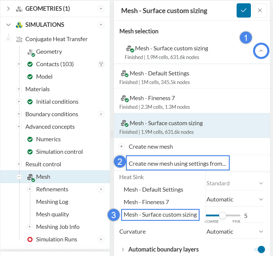
- Click on the arrow to access the mesh menu
- Click on Copy mesh settings from…
- Select the third mesh to copy all of its settings
After these steps, the fourth mesh can be set up. Click on the ‘+ button’ next to Refinements and create a Volume Custom Sizing. The Default sizing defines the target element size within a region. Please input ‘0.004’ meters.
Afterward, click on the ‘+ button’ next to Geometry primitives and select a Cartesian box.

Next, define the coordinates of the cartesian box, keeping in mind that it should fully cover the heat sink and chip. Consider the possible flow motion while deciding where to place the refinement region.

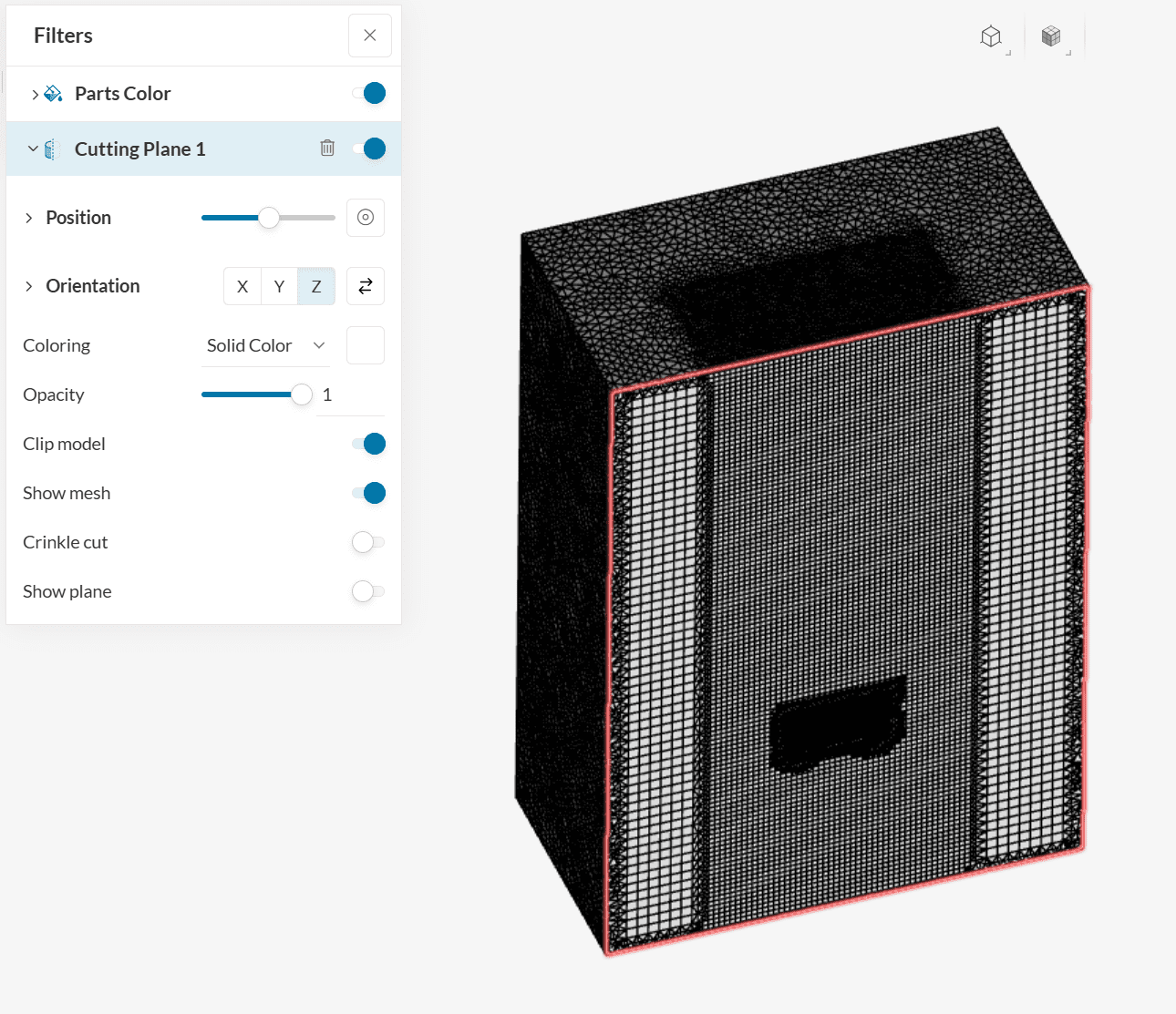
Go ahead and ‘Generate’ the fourth mesh. This one has an improved discretization around the heat sinks. To visualize it clearly, we can enter the mesh quality environment again:
3.5 Mesh Five: Inflate Boundary Layers
By default, the Automatic boundary layers option creates 3 layers. However, you can change all of the layer settings, giving you full control over the layer generation.
Please copy the settings from the previous mesh and configure the new mesh as below:
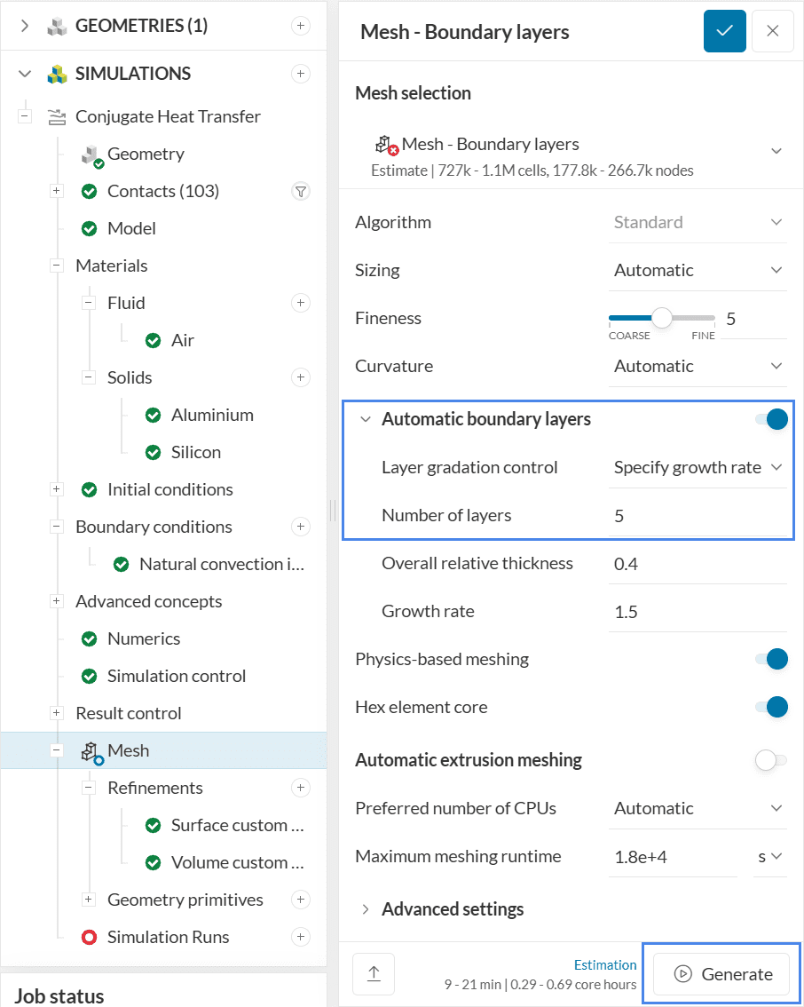
For this mesh, we will only adjust the Number of layers to ‘5’. It is also possible to easily control the Layer gradation by either specifying the Growth rate or the First layer thickness. After adjusting the number of layers, we are ready to ‘Generate’ the fifth mesh.
The extra layers can be seen with a mesh clip. With this configuration, the near-wall profiles are captured more accurately.
3.6 Mesh Six: Advanced Settings
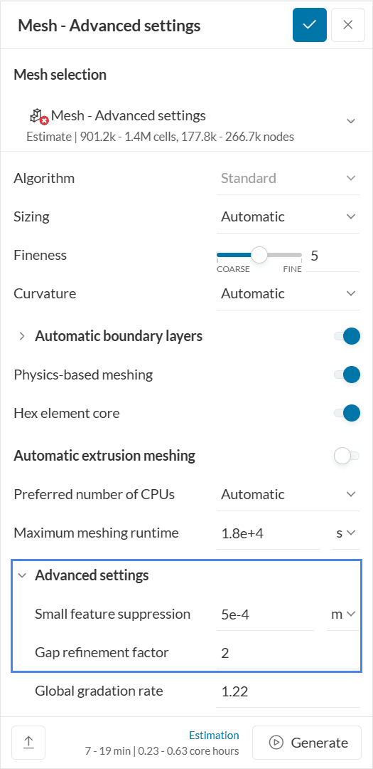
By expanding Advanced settings, you will find three additional parameters:
- Small feature suppression represents a threshold to ignore small entities. Only entities larger than the input value are meshed.
- The Gap refinement factor represents the number of cells in small gaps. It doesn’t necessarily have to be an integer.
- Finally, the Global gradation rate is the ratio between the size of two adjacent cells. In short, it controls how fast the mesh transitions from small to large cells. The default setting is 1.22 – smaller values result in a smoother transition, whereas larger values cause a faster transition.
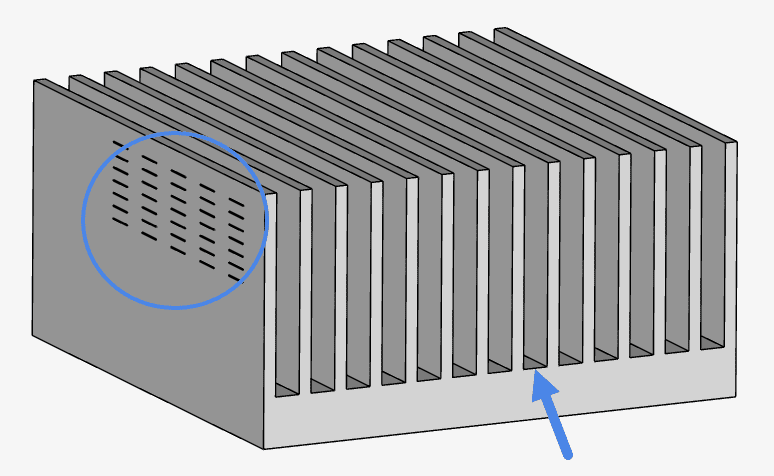
On one of the sides of the heat sink, a lot of small features are present. Their smallest edge has about 0.2 mm of length. Naturally, gaps are also present, between the fins.
To see how both advanced settings work, please copy the settings of the very first mesh from this tutorial. Change Small feature suppression to 0.0005 meters and the Gap refinement factor to 2.
Comparing the first mesh to the advanced settings mesh, the differences can be seen clearly:
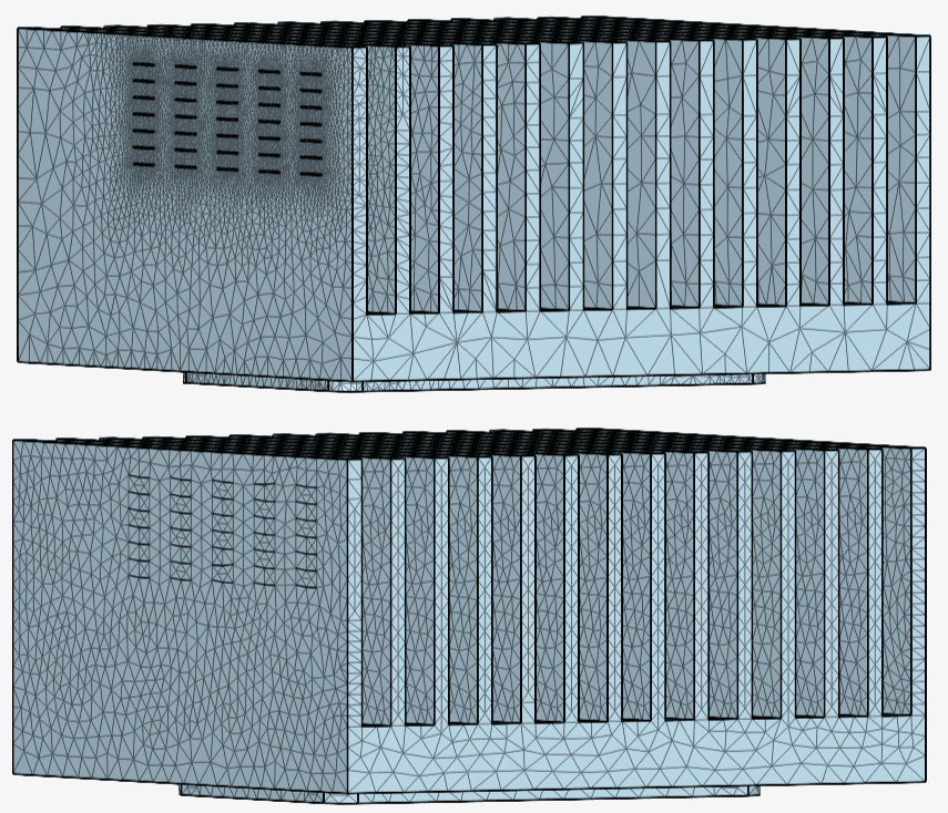
The 2 gap elements improve the discretization of the gaps between the fins, while the small feature suppression prevents the small faces from being meshed.
The small feature suppression setting can be particularly helpful when the CAD models are not very clean.
Congratulations! You have finished the standard meshing tutorial!
Note
If you have questions or suggestions, please reach out either via the forum or contact us directly.
Last updated: October 20th, 2025
Did this article solve your issue?
How can we do better?
We appreciate and value your feedback.


