Located in the Physical contacts settings, Fictitious clearance is a feature that inserts an imaginary material between contacting surfaces. This material has no stiffness, and its thickness typically changes as a function of time.
When computing the signed contact distance, the solver subtracts the imaginary material’s thickness from the actual geometrical distance. This result is used to evaluate contact forces and determine whether the contact is open or closed.
Fictitious clearance documentation
To learn more about the Fictitious clearance setting, refer to the dedicated Physical contacts page.
EXAMPLE 1: Pre-stress generation on a bolt
A common application for Fictitious clearance is generating pre-stress. For example, you can simulate bolt tension by inserting an imaginary layer of material between the bolted plates, causing the bolt to stretch beyond its initial state. Accurately simulating this behavior and evaluate all parts in the assembly using standard boundary conditions is not possible, as they would introduce spurious stiffness into the system.
Consider the following example, where pre-stress is generated on metal sheets connected by a bolt.
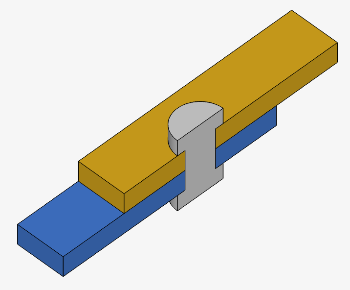
To apply this configuration, follow these steps:
- Assign a ‘Physical contact’ between the two surfaces.
- Enable ‘Fictitious clearance’ by selecting Yes beside the feature name.
- Apply the clearance to either the Master or Slave surface. In this example, ‘Master’ is arbitrarily chosen. The clearance value will grow as the simulation progresses, according to the equation 1.5e-4 * t [m].
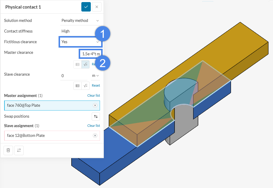
Once the simulation begins, the master nodes will move in the opposite direction of the master face. In this example, the master face moves in the upward direction (along the positive z-axis).
The Animation below shows the generated pre-stress by plotting the Parts color showing the ‘Von Mises stress’ field, as well as the sheets separating due to the Fictitious clearance.
EXAMPLE 2: Gradually removing part interference (interference fit)
Another notable application of Fictitious clearance is for interference fit simulations. A common scenario requiring an interference fit is modeling how a seal fits into a cavity, since its original shape differs significantly from its shape after the system is assembled. A simpler example is a pin constrained by a smaller hole via interference.
Consider the scenario presented in the Figure below. In CAD, an artificial interference was established between the pin and the plate.

To resolve this interference so the part surfaces perfectly match, you could simply assign a ‘Physical contact’ to the interfering surfaces and run the simulation. However, this often introduces a high force instantaneously, producing extreme stresses and strains—sometimes even pushing the material into the plastic regime—which can cause the simulation to fail. To prevent this, Fictitious clearance can be strategically applied to gradually ramp up the interference.
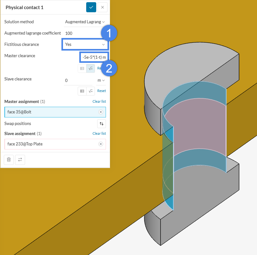
Apply this configuration using the following steps:
- Assign a ‘Physical contact’ between two surfaces.
- Enable ‘Fictitious clearance’ by selecting ‘Yes’ beside the feature name.
- Apply the clearance either to the Master or Slave surface. In this case, the ‘Master’ will be arbitrarily chosen and the clearance value will decrease as the simulation progresses according to the provided equation -5e-5*(1-t) m.
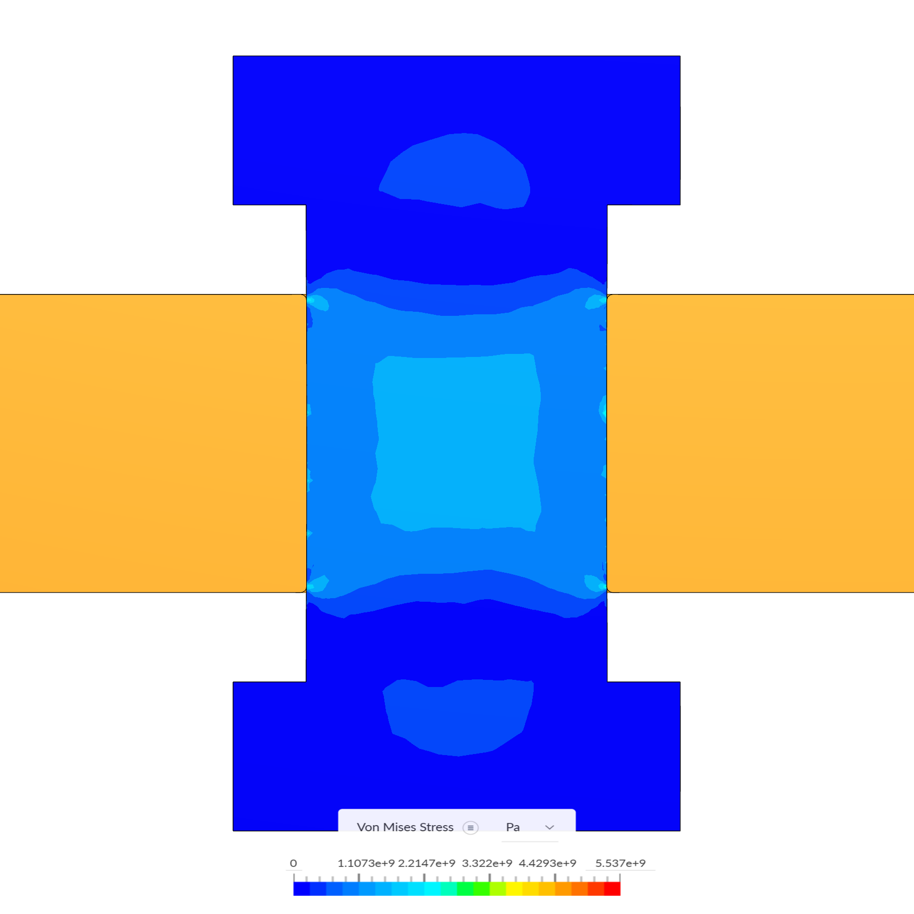
The Figure below shows the final Von Mises stress after the Fictitious clearance value equals 0 at t = 1.0 s, and the Animation below it shows it decreasing as the simulation progresses.
What does a negative fictitious clearance mean?
While most users easily grasp a positive Fictitious clearance—visualized as an invisible material layer sandwiched between surfaces—negative values can be more abstract. A helpful analogy for a negative clearance is a switch. A negative value means the Physical contact allows parts to overlap without switching “on,” until the clearance magnitude becomes smaller than the actual physical interference.
Consider an example where a pin and a hole interfere by 0.5 mm. In CAD, these two parts literally share the overlapping radial volume. Without simulation contacts, the parts would pass through each other like ghosts. However, if we apply a ‘Fictitious clearance’ using the formula -0.5 * (1 – t), the solver gradually resolves the overlap. At t = 0.1 s, the calculated clearance is -0.45 mm, meaning the solver only attempts to resolve a penetration of 0.05 mm. By t = 0.2 s, the clearance is -0.4 mm, resolving an interference of 0.1 mm, and so on.
Please visit the documentation page to learn more about physical contacts in structural analyses.
Note
If none of the above suggestions solve the problem, please post the issue on the forum or contact us.


