This article explains how to create cell zones during CAD preparation and how to represent them during the meshing stage.
What Is a Cell Zone and Why Is It Needed?
In a CFD simulation, the solid and fluid domains are divided into small control volumes through a process known as meshing. A cell zone is a designated 3D region within the mesh that groups cells according to how the CAD geometry is defined. By assigning cells to a specific zone, it becomes possible to apply targeted properties or physical models to that region. With the cell-zone approach, the cells within the defined region can represent a:
- Permeable heat source (Power sources)
- Momentum source (Momentum sources)
- Porous region (Porous media)
- Rotating region (Rotating zones)
- Thermal resistance network
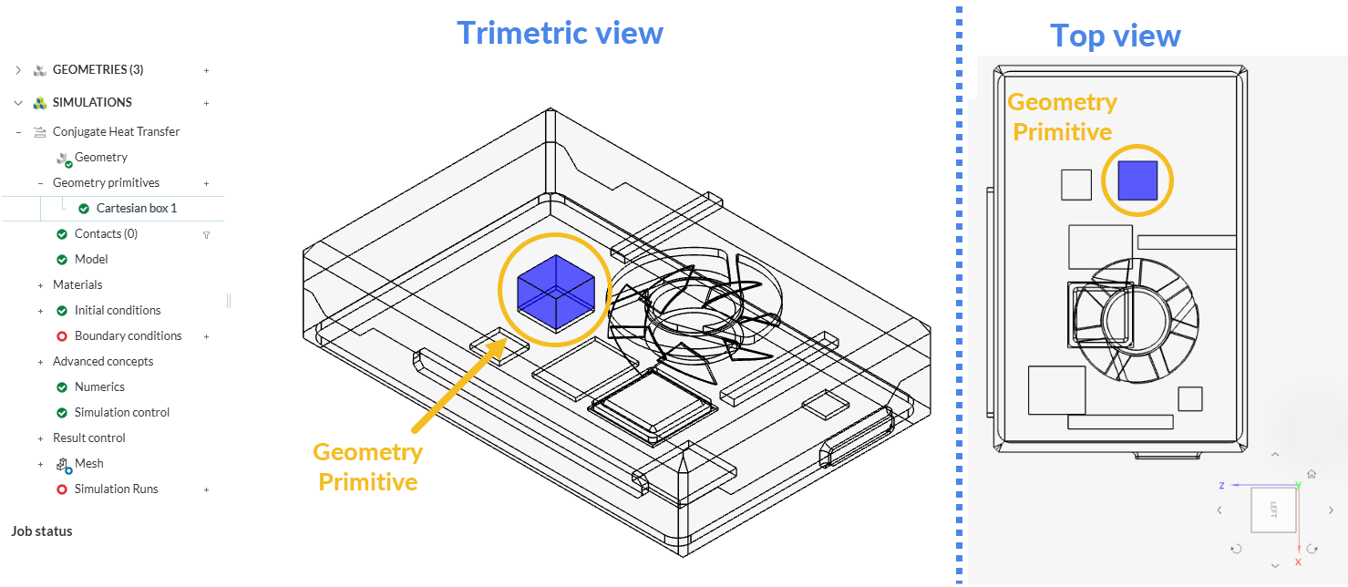
In SimScale, geometry primitives (Box, Cylinder, Sphere) can be used to define regions for advanced concepts such as sources or porous media. This approach allows a cell zone to be set up without preparing a dedicated CAD body. However, primitives come with two important limitations. First, they are restricted to simple shapes. Second, they do not create physical boundaries in the mesh—meaning the primitive’s limits may cut through existing cells, so the zone may not align cleanly with the mesh topology.
When a more precise or geometrically complex region is required, a solid body representing the advanced concept must be created. This can be done in two ways:
- Creating the solid directly in SimScale.
This approach is suitable when the region still resembles one of the primitive shapes. Although SimScale’s CAD Edit does not support sketch-based modeling, it enables the construction of more complex geometries through operations such as those available in the Boolean Group. It also supports face extrusion, body rotation, and similar transformations to generate new solid bodies. - Creating the solid in an external CAD tool.
This option provides the full flexibility of traditional CAD modeling, allowing complex operations and arbitrary geometries that may be difficult or impossible to construct within SimScale.
Keep in mind!
Geometry primitives cannot be used to define rotating zones. To set up rotating zones in a simulation, refer to the dedicated Knowledge Base article How to Prepare the CAD for Simulating Rotating Zones?
Example: Electronics Casing
Consider the following scenario. A heat sink is modeled inside an electronics casing, with the fluid passing through the casing via air gaps. The heat sink’s function is to transfer heat efficiently into the fluid domain.
Using SimScale’s geometry primitives feature, the heat sink can be simplified as a Cartesian box. This is only possible if the box is aligned with the x, y, and z axes.
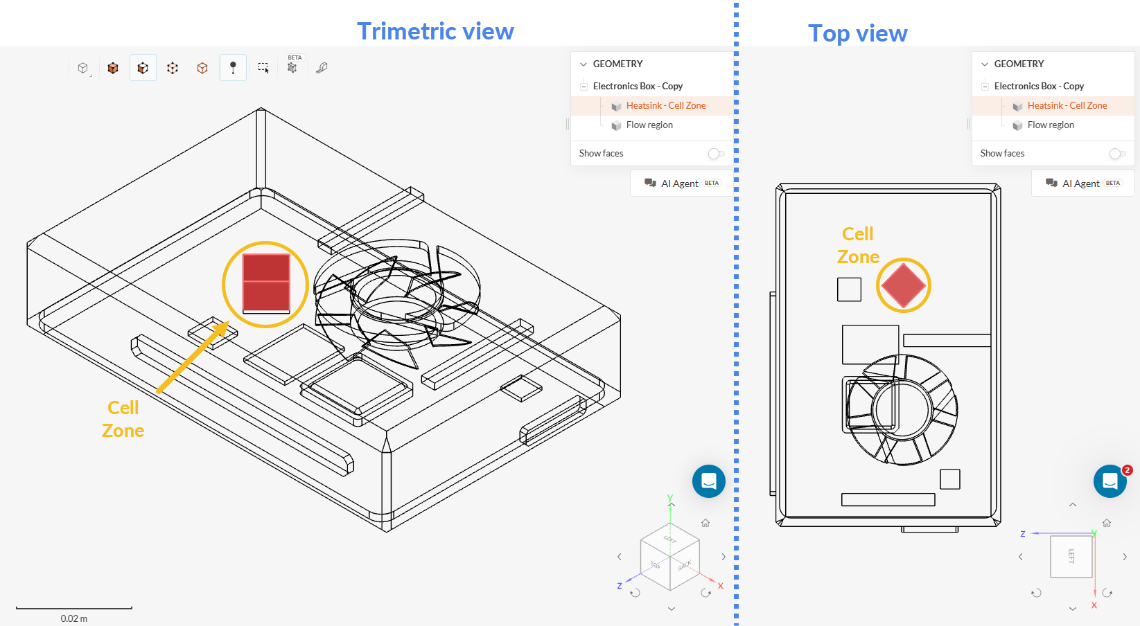
Now consider a second scenario, in which the heat sink is not aligned with the x, y, and z axes. In this case, a part volume around it must be created in a local CAD software. This volume will be treated as a cell zone once the CAD model is uploaded to the SimScale Workbench. This part volume will be visible under the scene tree as an individual part, with the same name it had in the CAD software.
To create a cell zone, the flow domain must first be created. Some CAD tools already have a flow volume extraction feature. The fluid domain can be created either in the CAD software or in SimScale’s CAD Edit Tool.
Approach 1: Create the Flow Region and Cell Zone in Your CAD Tool
Once the fluid region is ready, the next step is to create a cell zone. In this example, a simple box is created on the chip face to represent a permeable power source. The same method can be used to define the cell zone for momentum sources and porous media regions.
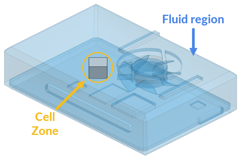
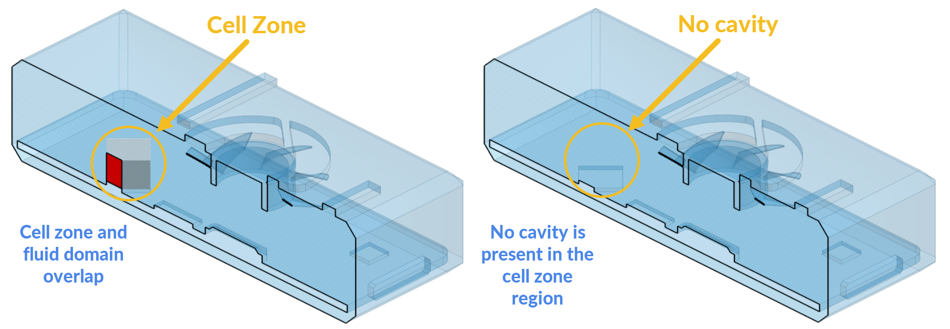
As stated earlier, the cell zone is only a part used to define the region inside the fluid domain. This means the cell zone part must overlap the fluid domain. In other words, the cell zone should not be subtracted from the fluid domain. In the following picture, the cutting view of the cell zone and fluid domain is shown. The interference (overlap) between the cell zone and the fluid region is highlighted in red. If the cell zone is hidden (the picture on the right), this region does not produce a void or cavity in the fluid region.
Approach 2: Create the Cell Zone in Your CAD Tool and the Fluid Region in SimScale
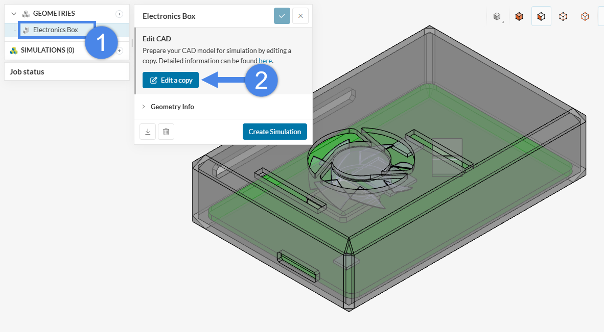
If the cell zone is already modeled in the CAD model, the fluid region can be created in SimScale. First, create the cell zone in the CAD tool, then import the CAD model to SimScale’s CAD Mode:
In this example, the air inside the electronics casing is modeled, therefore the Interval flow volume operation needs to be selected:
Did you know?
If the model has no enclosure, the External Flow Volume operation can be used to create the fluid domain.
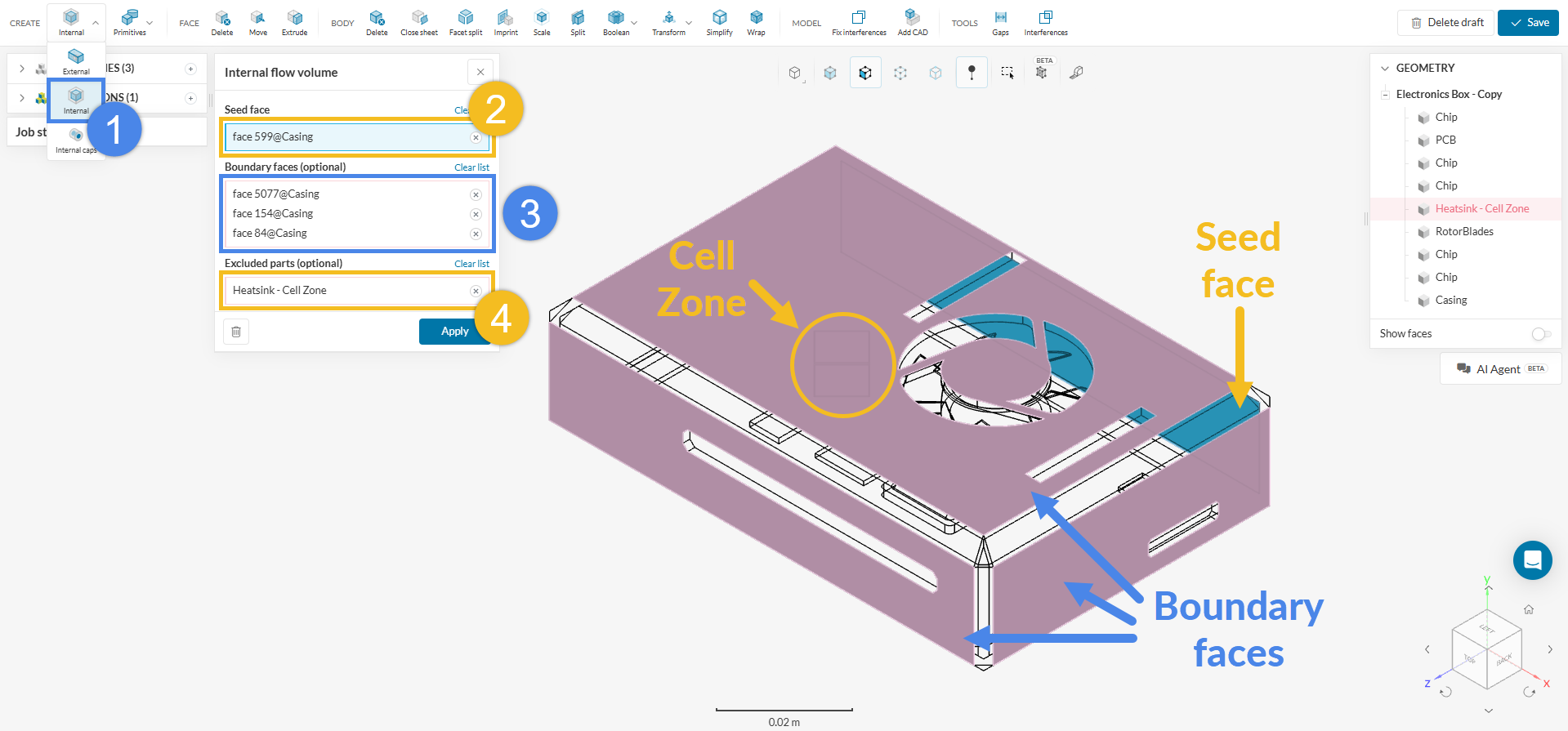
- Create an Internal flow volume extraction operation.
- As Seed face, assign one of the internal faces that is inside the fluid region and in contact with one of the openings.
- Under Boundary faces, assign the boundary faces around the openings. Refer to this article if you are unsure about the boundary faces of the geometry.
- Assign the cell zone part in the Excluded parts tab.
- Press ‘Apply’ to run the operation.
At this point, a volume named Flow region is created in the scene tree on the top right. Depending on the analysis type planned, one of the following options can be used:
- For a Conjugate Heat Transfer analysis, the existing geometry, which includes the solid parts, can be used.
- For Incompressible, Compressible, or Convective Heat Transfer analyses, the solid parts must be deleted using the Delete feature in the CAD mode:
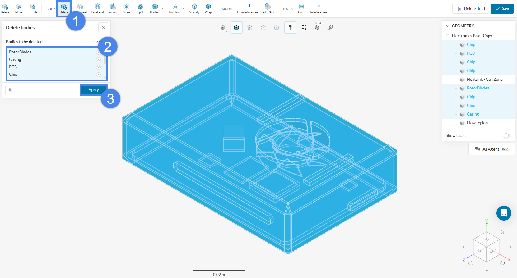
- Pick the ‘Delete’ operation under BODY.
- Select all the solid parts. Note that two volumes remain unselected: the flow region and the cell zone.
- Hit ‘Apply’.
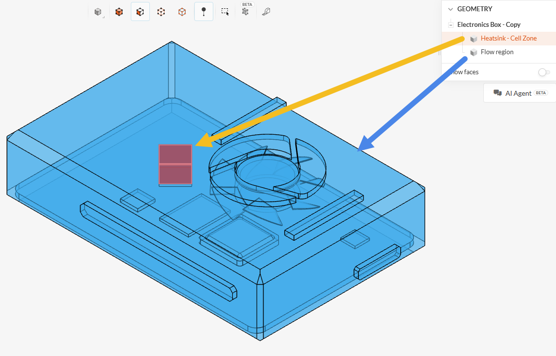
- The final model should only include the flow region and the cell zone. Click ‘Save’ to export the new CAD version to the Workbench.
Did you know?
Except for the Conjugate Heat Transfer Analysis, all solid parts must be removed from the fluid domain. In a CAD model correctly prepared for simulations with a cell zone, the flow region contains the negative of the solid parts.
Approach 3: Create the Cell Zone and the Fluid Region in SimScale
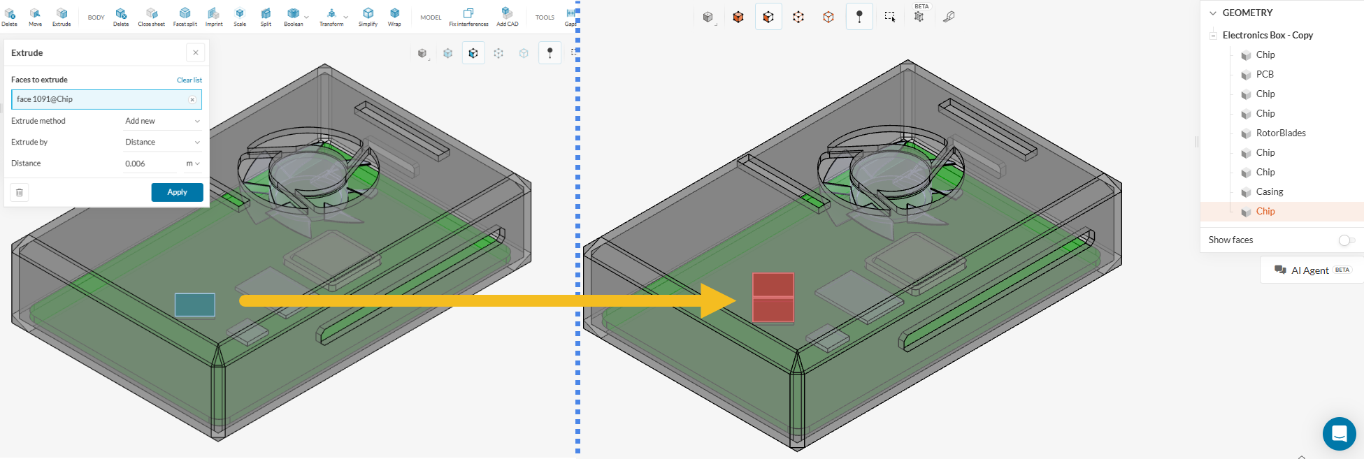
In some cases, it is also possible to create the cell zone directly in SimScale using CAD Edit features. For a hypothetical electronics box where the cell zone can be obtained by a face extrusion, the face beneath the cell zone can be extruded by choosing the “Add new” Extrude method, as shown in the figure below. Note that, in this case, the new solid receives the same name as the solid from which it originated, i.e., the solid that originally contained the extruded face.
This procedure generates an extra solid in the assembly, which corresponds to the cell zone. The steps outlined in Approach 2 can then be repeated to generate the flow region by selecting the newly created cell zone as an Excluded Part.
Note on cell zone creation within SimScale’s CAD Edit environment
The methodology described above, in which a face is extruded to generate a solid part to be used as a cell zone, is only one valid option for this specific example. In other cases, other tools may be useful, such as generating boxes and cylinders and applying subsequent boolean operations to obtain the desired shapes.
Assigning Cell Zones in Workbench
Cell zone assignment depends on the mesh type in use.
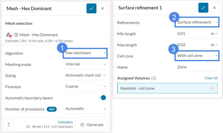
1- If the Hex-dominant or Hex-dominant parametric mesh is in use, create a surface refinement. In the Cell zone option, select ‘With cell zone’.
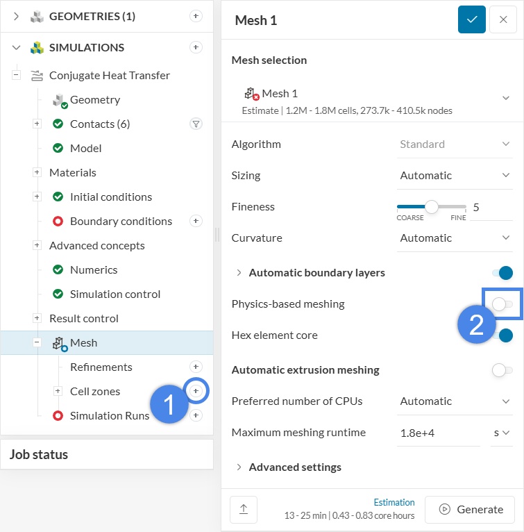
2- If the Standard mesh is in use, there are two ways to define the cell zones.
- Enable the Physics-based meshing toggle. In this case, the cell zones are automatically identified.
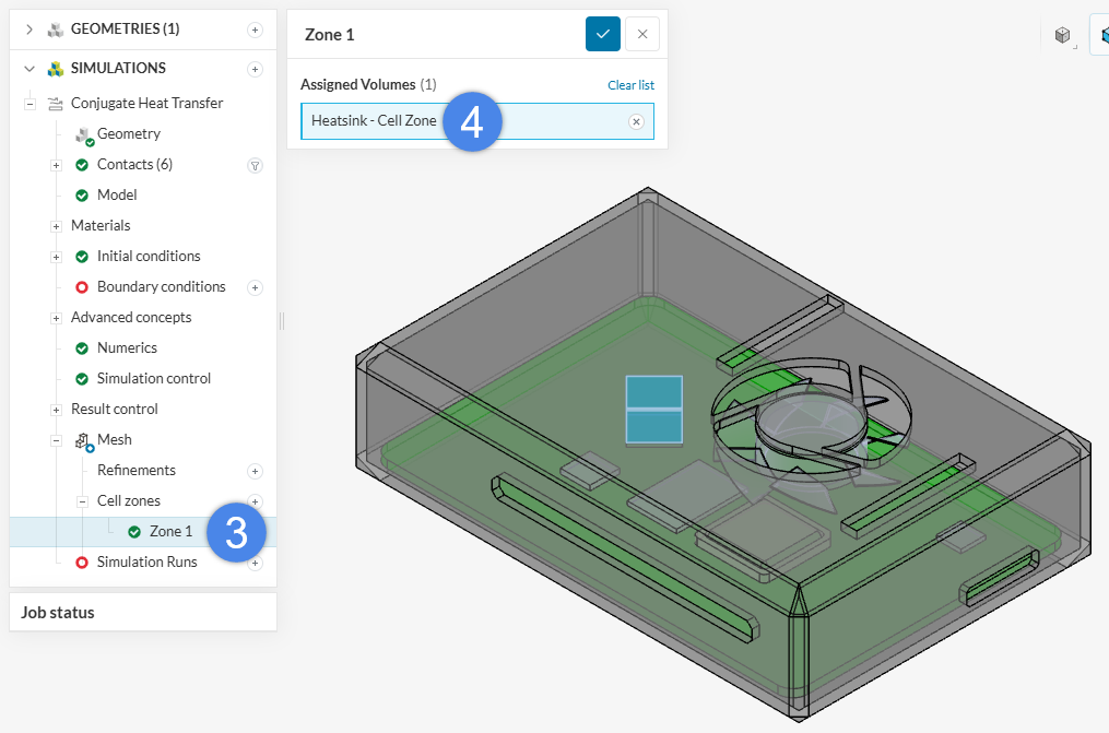
- If the Physics-based meshing toggle is disabled, the Cell zone feature appears under the Mesh feature and the cell zones must be assigned manually:
Note
If none of the above suggestions solve the problem, post the issue on the forum or contact the support team.