Documentation
A thermal resistance network can be used to approximate the effect of heat sources and heat transfer from that source to the surrounding domain without explicitly having to resolve the source geometry itself. An example application is a PCB with multiple small resistors, LEDs, and/or processor chips mounted on top, which, compared to the overall domain, are small enough for their individual geometry to play only a minor role on the result.
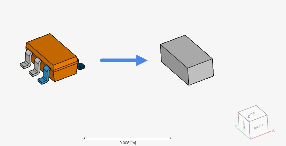
In the image below, the left-hand side model represents a complex geometry containing several leads and a casing, whereas the right-hand side geometry shows a simplified version of the geometry, which is good for a simulation with thermal resistance network:
Did you know?
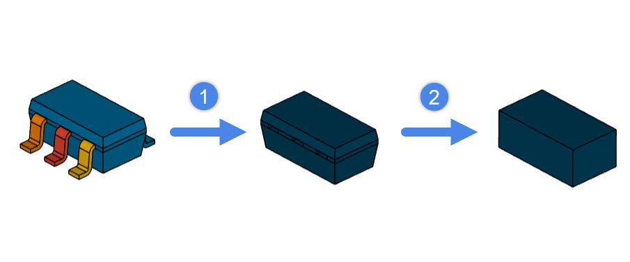
It is possible to perform the CAD clean up from Figure 1 in the CAD mode environment. It would take 2 simple operations:
1. Deleting the leads with a Delete body operation
2. Running a Simplify operation in Box mode. As the name suggests, this operation simplifies a complex geometry with a simpler entity.
The figure below shows how the geometry looks like, after each step:
The thermal resistance network assumes a simplified thermal model. Two models are available in SimScale: the Star Network Resistance Model, and the Two Resistor Model.
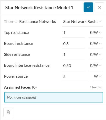
For the Star Network Model, the resistance between the top face and bounding region, side faces and bounding region, as well as bottom face and bounding region can be specified. For the Two Resistor Model, the user cannot set Side resistances, as the sides are assumed adiabatic.
Here is an example of the setup of a Star Network Resistance Model:
Assignment of Thermal Resistance Networks
Components set with resistance network cannot be assigned with material properties. If a part is assigned to a material and a resistance network the simulation won’t be able to start due to the validation of multiple assignments to one part. The Simulation will show the following error message: “The following entities of thermal resistance network(s) have been assigned to other settings. Please remove these assignments: part1″
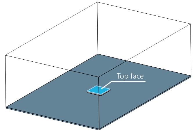
Note that, in the image above, the assignment contains a single face (the top face). For clarification of each resistance term, the diagram below depicts the thermal resistance model:
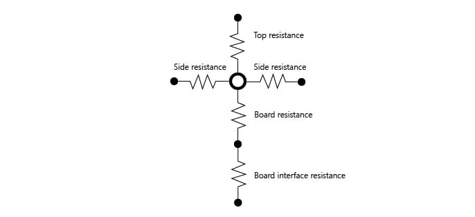
For all four side faces, a single thermal resistance value needs to be specified. For the top and bottom faces, one additional resistance component can be specified. In case there is a thermal conduction paste between the board and the chip, it’s possible to define it as a Board interface resistance.
Important
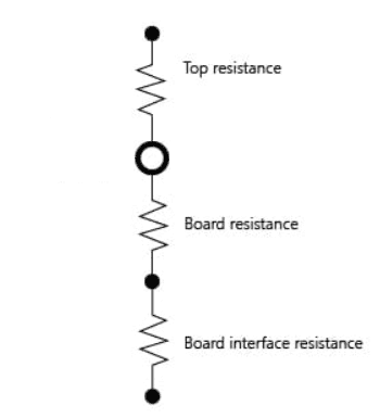
The main difference between the Two Resistances and the Star Network Resistance models in SimScale are the side resistances. The image below shows the representation for the two resistor model:
As important notes, the topology that is assigned to a thermal resistance network is not going to be resolved in the mesh, since it is treated as a cell zone. Additionally, all contacts defined between topology assigned to thermal resistance networks and surrounding regions will be ignored, meaning thermal resistance networks are always taking priority over contacts.
In the background, for each set of faces (top, sides, and bottom), the following calculation takes place:
Important
A thermal resistance network relies on calculating the heat flux across interfaces with neighboring regions. This is only possible if all faces of the body are defined as interfaces. In other words, every face must be in contact with another region (solid or fluid) so that heat can enter or exit through it.
This way, a realistic behavior for the heat flux is achieved through each one of the boundaries.
Note
When creating a simulation run, a warning will be shown that some faces have been assigned to both a thermal resistance network and an interface. This warning can be ignored. The simulation will prioritize thermal resistance networks over contacts.
If you are interested in a comparison between a simulation using the thermal resistance network model and a simulation with detailed geometry, make sure to check this example project.
Last updated: September 1st, 2025
We appreciate and value your feedback.
Sign up for SimScale
and start simulating now