Remote Displacement
With the Remote displacement boundary condition, the guided displacement of a face or volume with a remote point can be specified. It provides advantages compared to the classical displacement boundary condition such as:
- A deformation behavior can be added to the assigned entity,
- A rotation condition can be applied to the assignment.
In SimScale, the Remote Displacement boundary condition has the following settings:
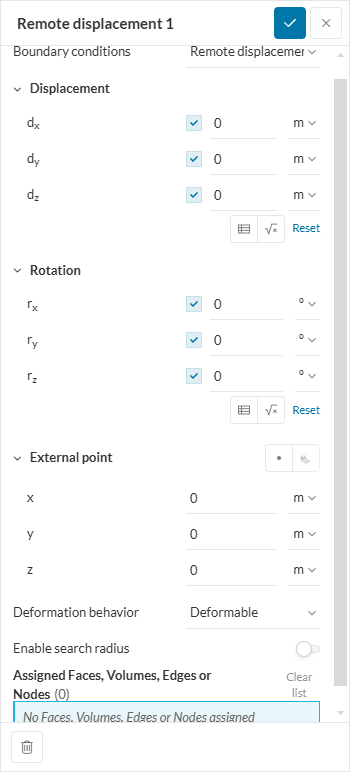
The parameters of the boundary condition are:
- Displacement: For each of the translational direction, the user defines if the displacement should either be unconstrained or predefined. Each predefined value can either be defined, in meters or inches, by a scalar value, a function, or a table. For function or table data the value may depend on time (or frequency in case of harmonic analysis) or the spatial coordinates.
- Rotation: For each rotational direction, the rotation can either be predefined or unconstrained. In the case of a predefined rotation, the value is given in radians or degrees. The input methods and possible dependencies are same as for displacement.
- External point: Here the user defines the coordinates of the external point on which the displacement is applied. The coordinates are given in the global coordinate system of the domain.
- Deformation behavior: This property defines if the assigned entities (edges or faces) may deform or if they are assumed to be rigid. When set to Deformable, no additional stiffness is generated on the applied entities. When set to Undeformable, the entity behaves like a rigid part. The connection of the point and the entities is a multi-point constraint which blocks all relative displacements between the affected nodes.
- Enable search radius: Enable search radius places a sphere with a user-defined radius on the external point. Only the nodes from the assigned entities that are inside of the sphere will be associated with the remote displacement boundary condition. This is often useful when assigning large faces to remote displacement boundary conditions, as it allows the user to limit the number of remote point connections and, therefore, memory requirements.
- Assignment: Set of faces or volumes where the remote displacement deformation will be applied.
Hint
If the deformable option is used and the number of nodes on the assigned entities is large (>1000), it is advised to use either the MUMPS or PETSC solver instead of Multfront since the performance of Multfront is not optimal for this kind of equations.
Supported Analysis Types
The following analysis types support the usage of the pressure boundary condition:
Remote Point Connections
Behind the scenes, the remote point is connected to all the nodes in the assignment with ‘spider web’ elements. As mentioned above, such elements can be completely rigid, in the case of Undeformable behavior, or flexible in the case of Deformable behavior. In the latter case, the remote point is connected to the nodes by RBE3-constraint.
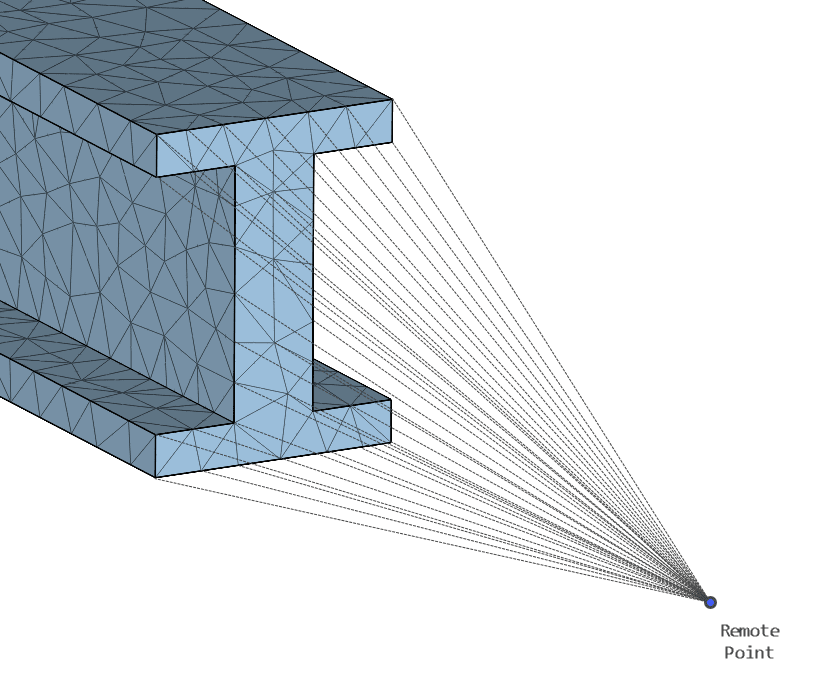
The specified degrees of freedom are applied to the remote point and broadcasted to the nodes in the assignment via the ‘spider web’ elements. The result is that this boundary condition allows the assigned face to be treated as a single entity, with its movement described with 6 degrees of freedom, constrained or imposed. For example, if the translation degrees of freedom are set to zero, and one rotational degree of freedom is left unconstrained, the assigned face is free to rotate around such an axis.
Limitations
This is a linear boundary condition, thus it is valid only if small displacements and rotations occur in the area of the applied entity and the remote point itself.
Also note that the more remote point connections you have, the more memory the solver requires. Associating large faces and/or heavily refined entities to a remote displacement may require larger machines to solve.
Example Applications
Some cases where the remote displacement boundary condition is often applied are:
- Simple supports over one face, where the rotation around one axis can be freed
- Guided displacement or rotation of the assigned faces or volumes
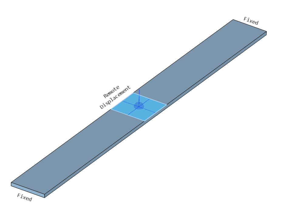
Deformation Behavior
To illustrate the difference in the effect of the deformation behavior, let’s see the example of a beam under imposed displacement, resulting in a deflected shape:
The deformed shapes for the cases of undeformable and deformable behavior below illustrate the difference between these two conditions. Especially, how in the former case the face remains flat while in the latter it deflects with the beam:
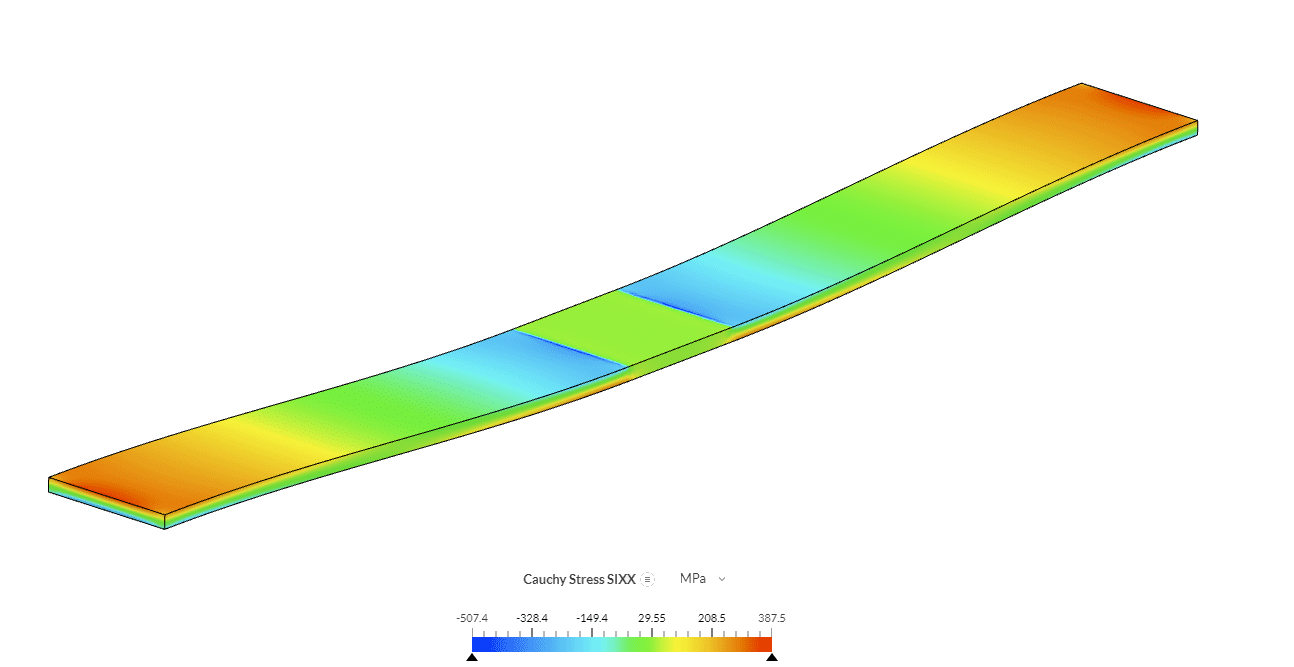
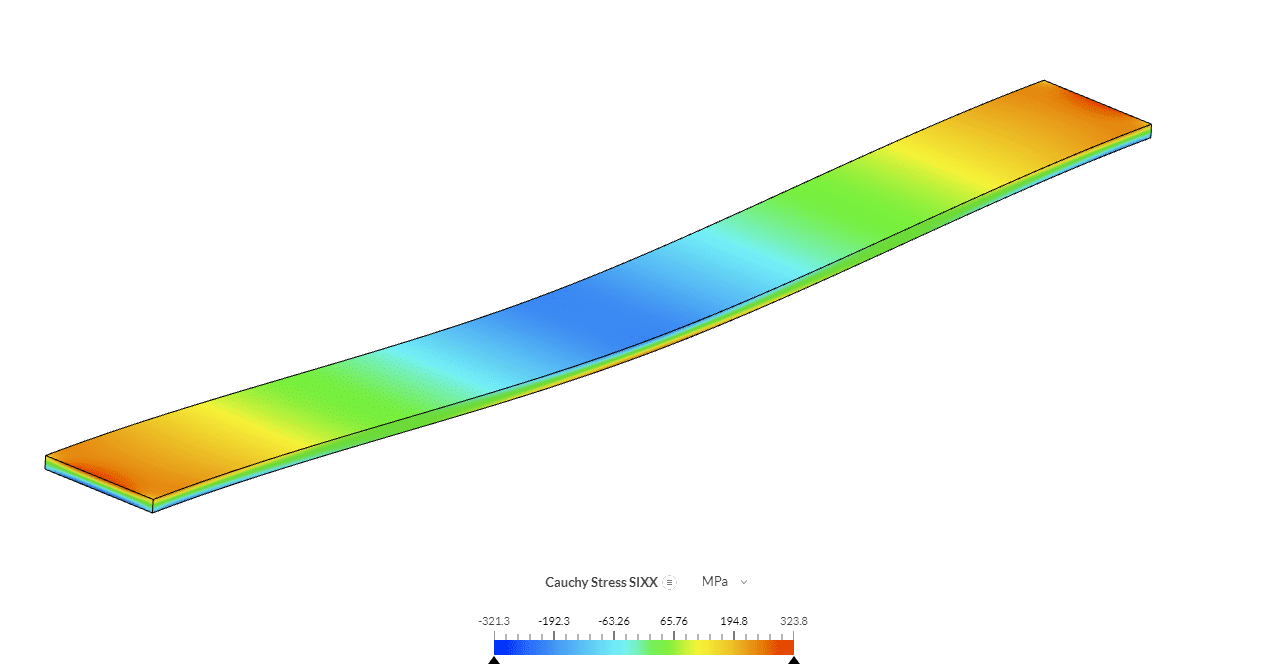
It is also notable how the undeformable behavior causes a stress discontinuity with respect to the deformable case, in which stresses are smooth and more in line with traditional beam deflection stress distribution.
Related Documentation
- Advanced Tutorial: Thermomechanical Analysis of an Engine Piston
- Validation Case: Static Analysis of an I-Beam Under Remote Force
- Validation Case: Pinned Bar Under Gravitational Load
Last updated: February 3rd, 2025
Did this article solve your issue?
How can we do better?
We appreciate and value your feedback.


