Documentation
This validation case belongs to solid mechanics. The aim of this test case is to validate the following parameters:
The simulation results of SimScale were compared to the results presented in [Schaum’s]\(^1\).
The geometry used for the case is as follows:
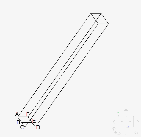
The bar is a square bottom with a cross-section area of 0.01 \(m^2\) and the length of the bar is 1.0 \(m\). Point B is located at the middle of the edge AC and point E is at the middle of the edge DF.
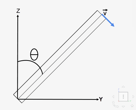
The bar is released from a 45° angle (\(\theta_{start}\)) and the velocity at the free end of the bar at 180° (\(\theta_{end}\)) is compared with the analytical solution from the document above.
Tool Type: Code_Aster
Analysis Type: Dynamic
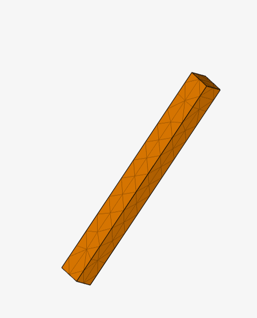
Mesh and Element Types:
The mesh for case A consists of 1\(^{st}\) order elements and it was created with the Standard meshing algorithm in SimScale with a region refinement applied.
| Case | Mesh Type | Number of Cells | Number of Nodes | Element Type |
| A | Standard | 216 | 104 | 1st order tetrahedral |
Material/Fluid:
Initial and/or Boundary Conditions:
The analytical solutions for stress and displacement are calculated with the equations below:
$$C = \frac{3g}{2l}{cos(\theta_{start})}\tag{1}$$
$$ \omega = \sqrt{\frac{3g}{l}{\left[cos\left(\theta_{start}\right)-cos\left(\theta_{end}\right)\right]}}\tag{2} $$
$$ v = l\omega \tag{3}$$
The equations used to solve the problem are derived in [Schaum’s].
The constant of integration C is given by equation (1). It is then used to calculate the angular velocity at the free end of the bar in equation (2) with \(\theta_{start}\) = 45° and \(\theta_{end}\) = 180°. With the angular velocity, the magnitude of the velocity can be calculated with equation (3).
The magnitude of velocity (\(v\)) obtained then is 7.08803 \(m/s\).
Comparison of the velocity obtained from SimScale against the reference results obtained from [Schaum’s]\(^1\) is given below:
| Case | Constraint Case | Schaum [\(m/s\)] | SimScale [\(m/s\)] | Error [%] |
| A | Remote displacement | 7.08803 | 7.08433 | -0.052 |
The velocity of the bar can be seen below:
Note
If you still encounter problems validating your simulation, then please post the issue on our forum or contact us.
Last updated: June 16th, 2025
We appreciate and value your feedback.
Sign up for SimScale
and start simulating now