Validation Case: Static Analysis of an I-Beam Under Remote Force
This validation case belongs to solid mechanics. This test case aims to validate the following parameters:
The simulation results of SimScale were compared to the results derived from [Roark]\(^1\).
Geometry
The geometry used for the case is as follows:
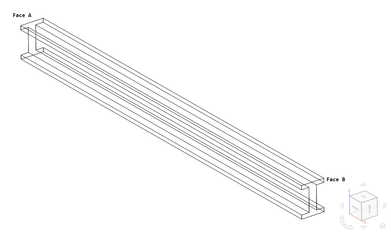
The beam has a length \(L\) of 1 \(m\), with the cross-section dimensions as shown:

| Parameter | Value [\(m\)] |
|---|---|
| B | 0.06 |
| H | 0.08 |
| b | 0.04 |
| h | 0.06 |
Analysis Type and Mesh
Tool Type: Code_Aster
Analysis Type: Static Linear
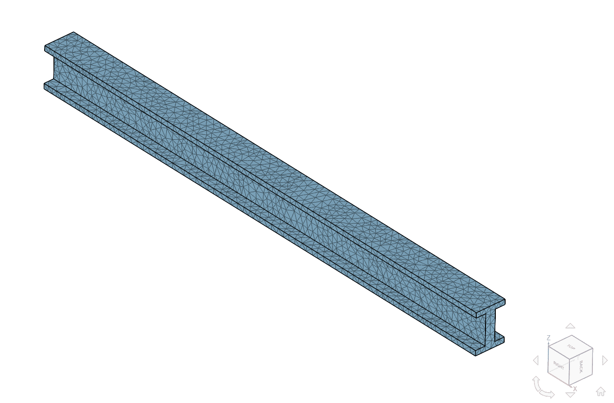
Mesh and Element Types:
Tetrahedral meshes were computed using SimScale Standard mesh algorithm and manual sizing. The table below shows an overview of the mesh characteristics.
| Case | Mesh Type | Number of Nodes | Element Type |
|---|---|---|---|
| A | Standard | 3345 | 1st order tetrahedral |
| B | Standard | 20742 | 2nd order tetrahedral |
Simulation Setup
Material:
- Linear Elastic Isotropic:
- \( E = \) 205 \(GPa \)
- \( \nu = \) 0.28
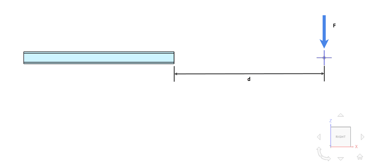
Boundary Conditions:
- Constraints:
- Face A is fixed
- Loads:
- Remote force of 1000 \(N\) applied at a distance \(d = \) 1 \(m\) on face B
Reference Solution
The analytical solutions for the deflection \(w\) at the free end of the beam are given by the following equations. The remote force \(F\) is substituted with a force and moment pair \(M\):
$${M = Fd} \tag{1}$$
$$ w = \frac{F L^3}{3 E I} + \frac{M L^2}{2 E I} \tag{2} $$
$$ I = \frac{1}{12} ( B H^3 – b h^3) \tag{3} $$
The computed reference solution is:
$$ M = 1000\ Nm $$
$$ I = 1.84×10^{-6}\ m^4 $$
$$ w = 2.209×10^{-3}\ m $$
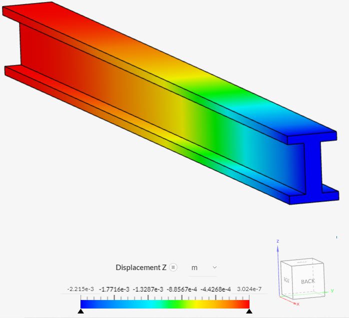
Result Comparison
Comparison of displacement DZ of the center point of face B with the computed reference solution \(w\):
| CASE | DZ [\(10^{-3}\ m\)] | \(w\) [\(10^{-3}\ m\)] | Error |
|---|---|---|---|
| A | 2.14109 | 2.209 | 3.07 % |
| B | 2.2121 | 2.209 | -0.14 % |
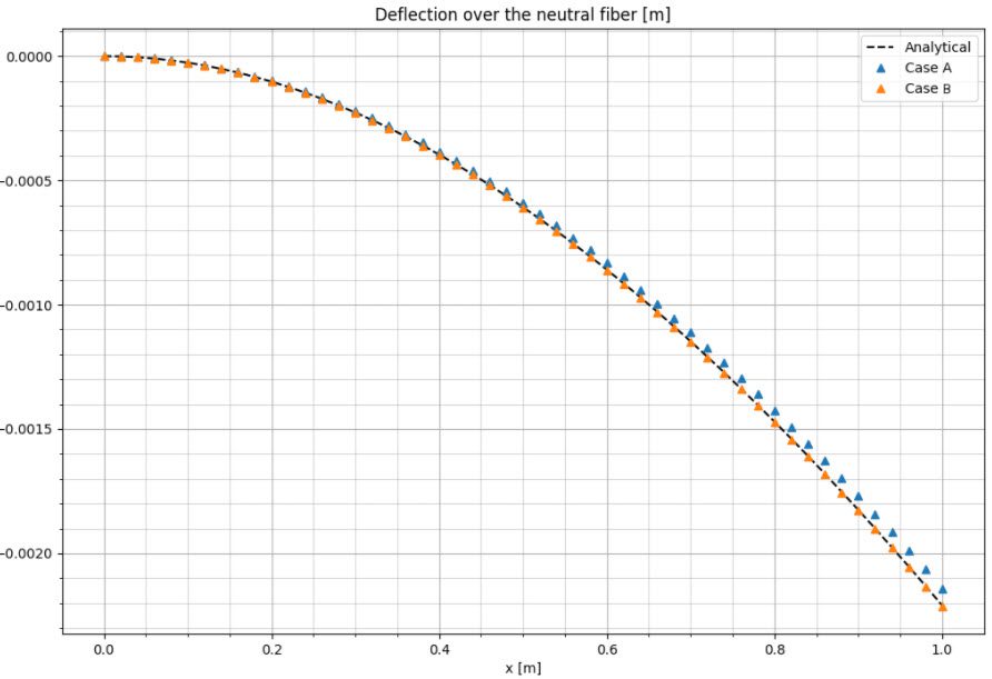
Comparison of the neutral fiber deflection shapes:
And finally, a plot showing the deformed shape and the magnitude of DZ displacement:
Related Tutorials
References
- (2011) “Roark’s Formulas For Stress And Strain, Eighth Edition”, W. C. Young, R. G. Budynas, A. M. Sadegh
Note
If you still encounter problems validating your simulation, then please post the issue on our forum or contact us.
Last updated: September 9th, 2022
Did this article solve your issue?
How can we do better?
We appreciate and value your feedback.


