Fill out the form to download

Required field
Required field
Not a valid email address
Required field
Required field
  • Set up your own cloud-native simulation in minutes.

  • Documentation

    Validation Case: Design Analysis of a Spherical Pressure Vessel

    This design analysis of a spherical pressure vessel validation case belongs to thermomechanics. This test case aims to validate the following parameters:

    • Transient thermostructural analysis

    The simulation results of SimScale were compared to the analytical results presented in [Afkar]\(^1\).

    Geometry

    The geometry consists of 1/8th of a sphere, with an inner radius of 0.19 \(m\) and an outer radius of 0.2 \(m\).

    sphere geometry for pressure vessel validation
    Figure 1: 1/8th sphere geometry used in the present validation project

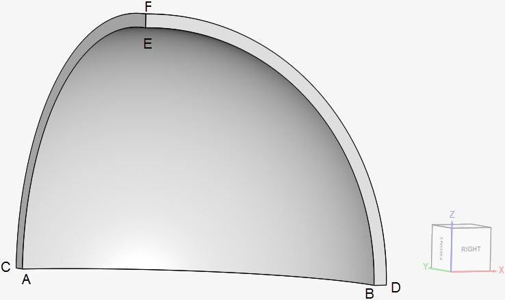
    The coordinates for the points in the sphere are as tabulated below:

    ABCDEF
    x00.1900.200
    y0.1900.2000
    z00000.190.2
    Table 1: 1/8th sphere dimensions in meters

    Analysis Type and Mesh

    Tool Type: Code_Aster

    Analysis Type: Transient thermomechanical, linear

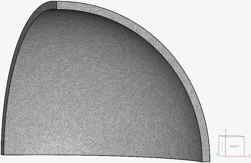
    Mesh and Element Types: The mesh for cases A and B was created with the standard algorithm, with first order elements.

    The setup from cases A and B is the same, except for the thermal conductivity \(\kappa\).

    CaseMesh TypeNodesThermal Conductivity \(\kappa\)Element Type
    (A)1st order standard17283320 \([\frac {W}{m.K}]\)Standard
    (B)1st order standard17283322 \([\frac {W}{m.K}]\)Standard
    Table 2: Overview of the mesh, creep formulation, and element technology used for each case

    Find below the mesh used for both cases. It’s a standard mesh with first order tetrahedral cells.

    first order standard mesh for a sphere
    Figure 2: First order standard mesh used for cases A and B

    Simulation Setup

    Material:

    • Steel (linear elastic)
      • \(E\) = 190 \(GPa\)
      • \(\nu\) = 0.305
      • \(\rho\) = 7750 \(kg/m³\)
      • \(\kappa\) = 20 \([\frac {W}{m.K}]\) and 22 \([\frac {W}{m.K}]\) for cases A and B, respectively;
      • Expansion coefficient = 9.7e-6 \(1/K\)
      • \(T_0\) Reference temperature = 300 \(K\)
      • Specific heat = 486 \(\frac {J}{kg.K}\)

    Initial Conditions

    Temperature is 300 \(K\) in the entire pressure vessel.

    Boundary Conditions:

    • Constraints
      • \(d_x\) = 0 on face ACFE;
      • \(d_y\) = 0 on face BDFE;
      • \(d_z\) = 0 on face ACDB.
    • Surface loads
      • Pressure boundary condition on face ABE. The pressure increases linearly from 0 \(MPa\) to 1 \(MPa\) according to formula \(P = (0.2e6).t\), where t is time from 0 to 5 seconds;
      • Fixed temperature value boundary condition on face ABE. Temperature is increasing linearly, from 300 \(K\) to 500 \(K\) according to formula \(T = 40.t + 300\), where t is time from 0 to 5 seconds;
      • Convective heat flux boundary condition on face CFD. The heat transfer coefficient is 90 \(\frac {W}{K.m^2}\) and \(T_0\) reference temperature is 300 \(K\).

    Reference Solution

    The analytical solution is given by the equations presented in [Afkar]\(^1\).

    Result Comparison

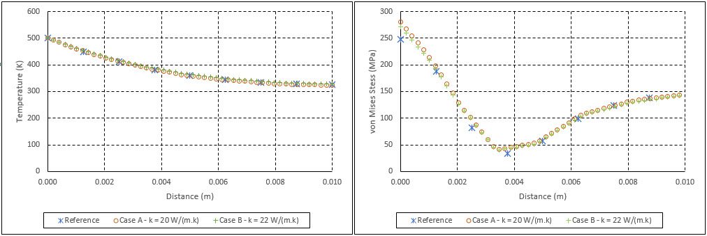
    Since no value for thermal conductivity \(\kappa\) was provided, the values of 20 \(\frac {W}{m.K}\) and 22 \(\frac {W}{m.K}\) were used. For the final time step, the SimScale results for von Mises stress \([MPa]\) and temperature \([K]\) over the edge EF are compared to those from [Afkar]\(^1\).

    spherical pressure validation result comparison
    Figure 3: Comparing temperature and von Mises stress results for cases A and B with those from [Afkar]¹.

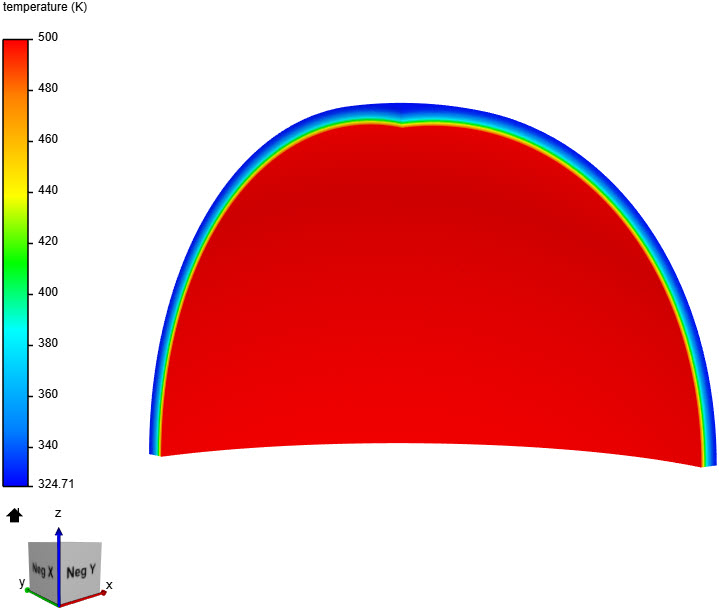
    In Figure 4, we can see how temperature is changing in the sphere’s width, for the last time step:

    temperature contours sphere validation
    Figure 4: Temperature on the 1/8th sphere, for time = 5 seconds

    Last updated: November 7th, 2023

    Contents