SimScale enables teams everywhere to innovate faster by exploring thousands of engineering decisions in seconds.
Helping the world’s best teams to engineer the irreplaceable
We’re on a bold mission to switch time from an enemy to an advantage for innovators like you that strive for engineering perfection.
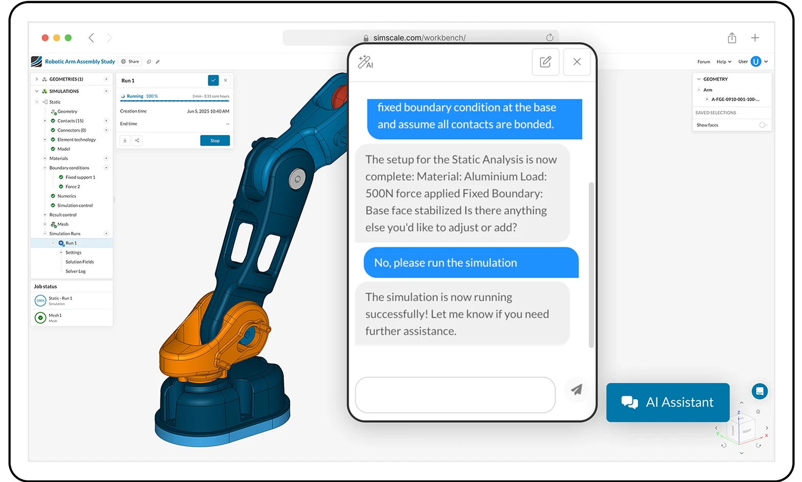
AI is built into the core of SimScale. Agents can automate simulation set-up, material selection, and design iteration, suggesting optimal parameters with intelligent guidance — enabling smarter design decisions faster than ever before.
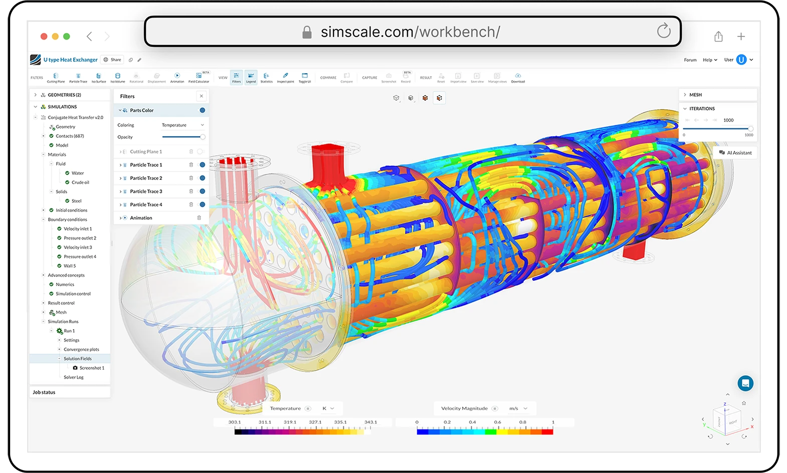
SimScale unites structural, fluid, thermal, electromagnetic, and multiphysics simulation in one platform. Surrogate AI models accelerate solver performance while maintaining trusted accuracy — so you can move seamlessly from rapid AI-led exploration to detailed full physics validation in a single environment.
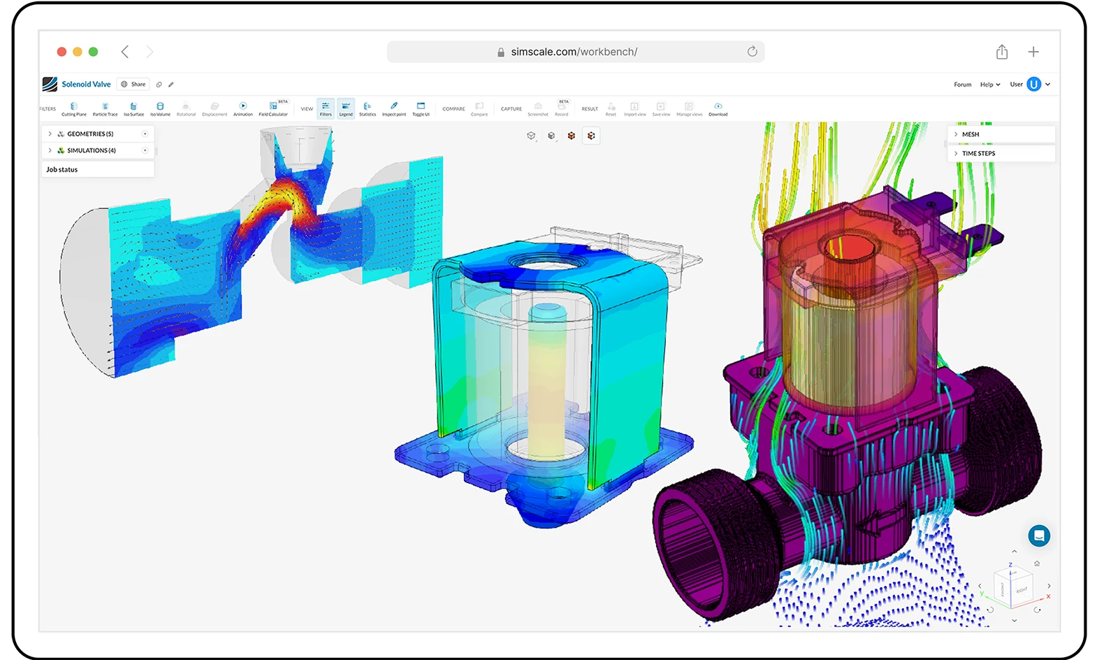
SimScale runs entirely in the cloud, giving every engineer instant access to powerful simulation and AI — no hardware or IT barriers. Elastic compute enables parallel simulations at any scale, while secure APIs and real-time collaboration keep teams connected and workflows seamless, all from your browser..
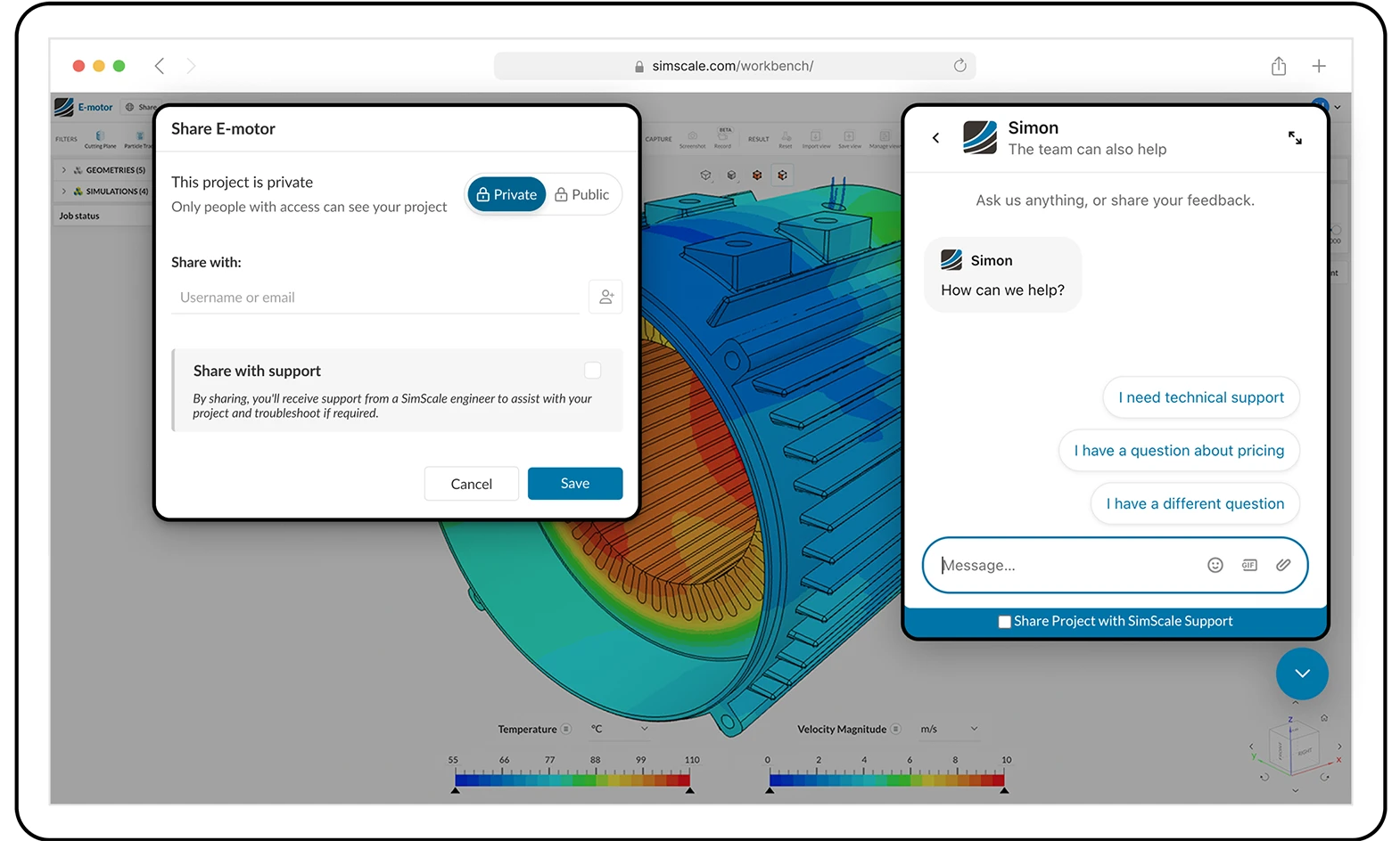
SimScale makes teamwork seamless with real-time model sharing and centralized management of data and best practices. Enjoy secure, governed access for every user, plus expert in-app support whenever you need it.

SimScale is an end-to-end solution but is also open by design. Our platform integrates seamlessly with your existing engineering tools, data, and AI agent layer, connecting CAD, solvers, system models, and data pipelines.
Unite AI, physics precision, and cloud scale in one engineering environment. From CAD import to optimization, run every step in your browser.
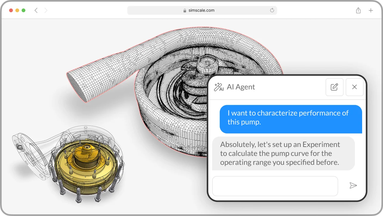
Cut down simulation lead time by automating manual steps
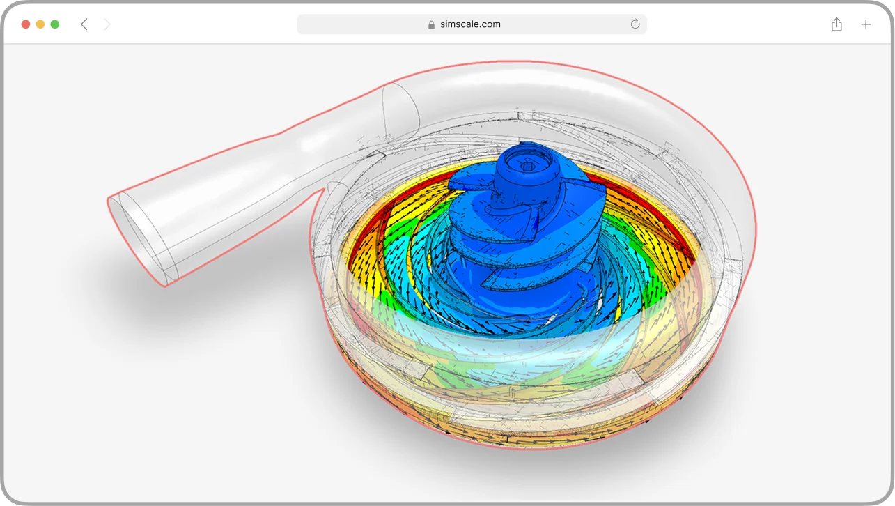
Use multiphysics simulation & AI prediction models in a unified cloud platform to map the design space.
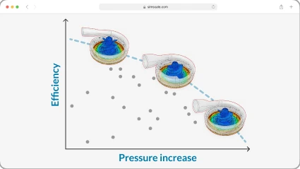
Compare thousands of designs instantly and iterate rapidly to the optimal solution
Speed up design cycles by 100x by exploring entire design spaces in seconds
Unlock innovation with AI-assisted iteration that tests and refines more product designs
Validate earlier with accessible, high-fidelity simulation to prevent costly late-stage changes.
Eliminate hardware and maintenance costs with scalable, browser-based simulation.
Product lifetime

More power output

Lower pressure drop

Lower aero drag

Force reduction

Faster design-to-prototype cycle
Faster development

Faster pre-testing

Faster time-to-result

Faster cycle time

Saved per experiment

Fewer prototypes needed

Lower costs vs. lab test

Lower hardware costs

Fewer lab prototypes
Material savings

Lower mfg. costs

Material savings (per unit)

Less energy used

Smaller turbine size

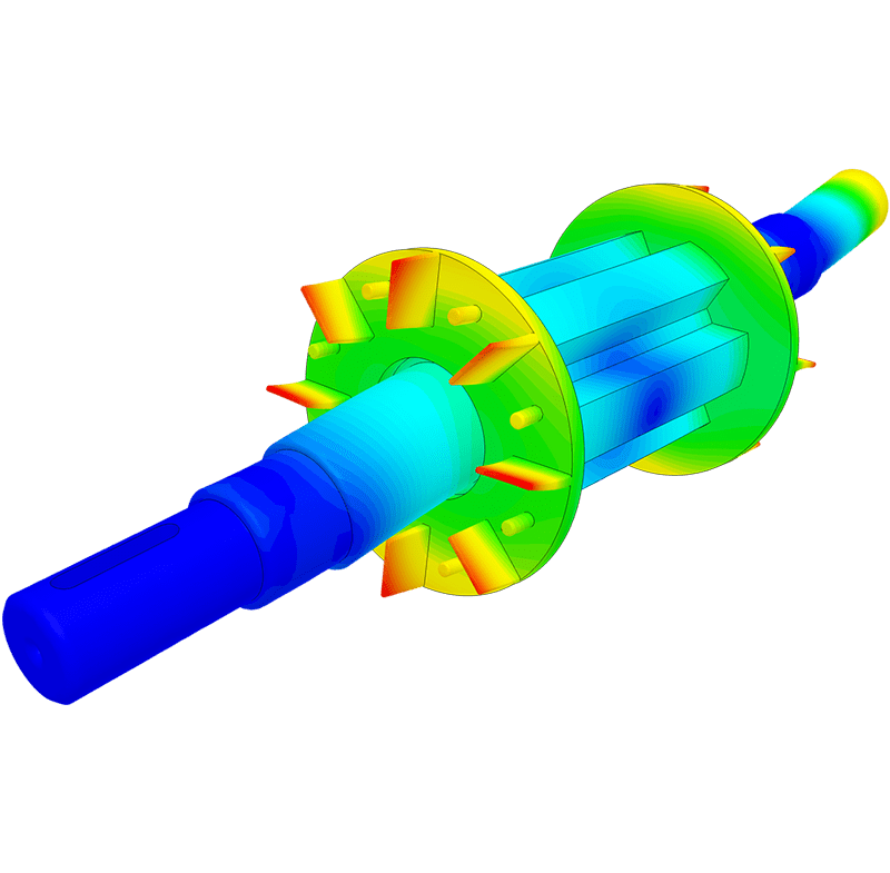
Stress & deformation, vibration, harmonic responses, transient dynamics, and more →
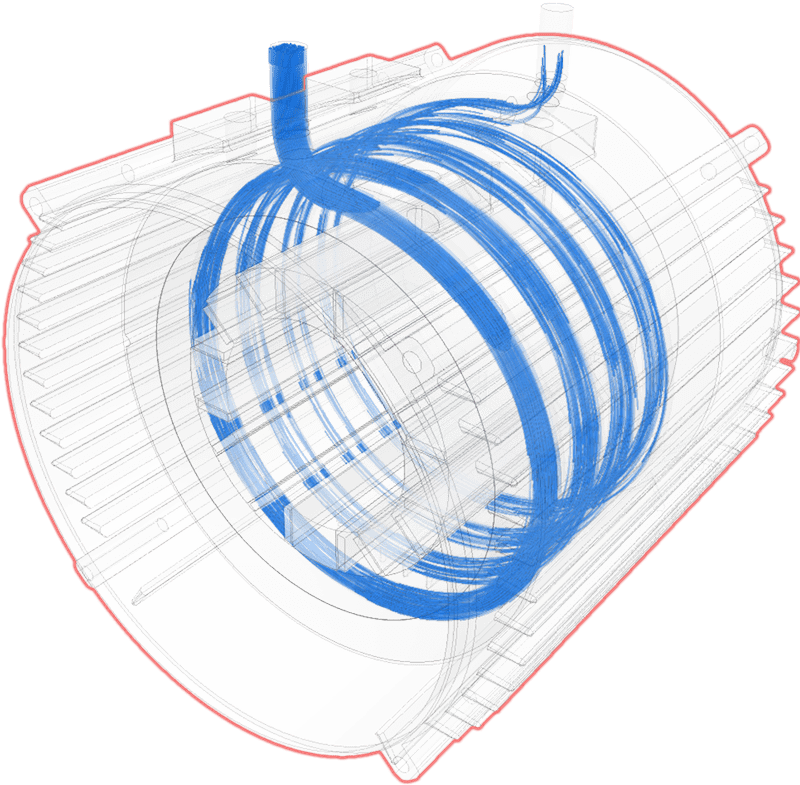
Single- & multiphase, gas & liquids, rotation & porous flow, and more →
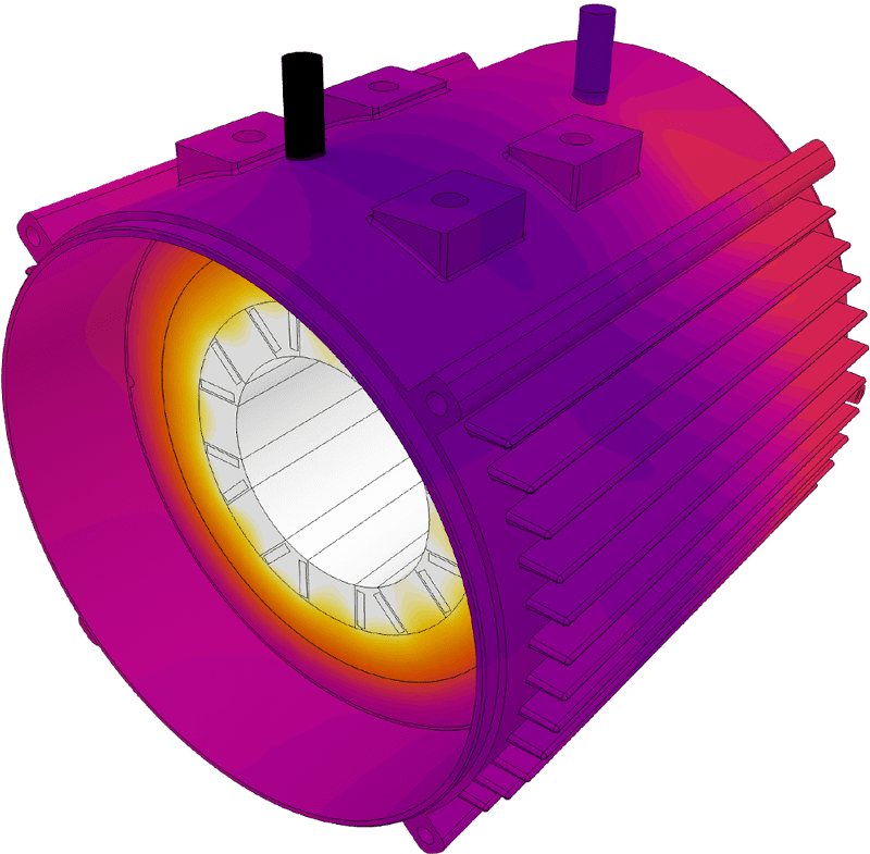
Conduction, convection, radiation — and all of them coupled →
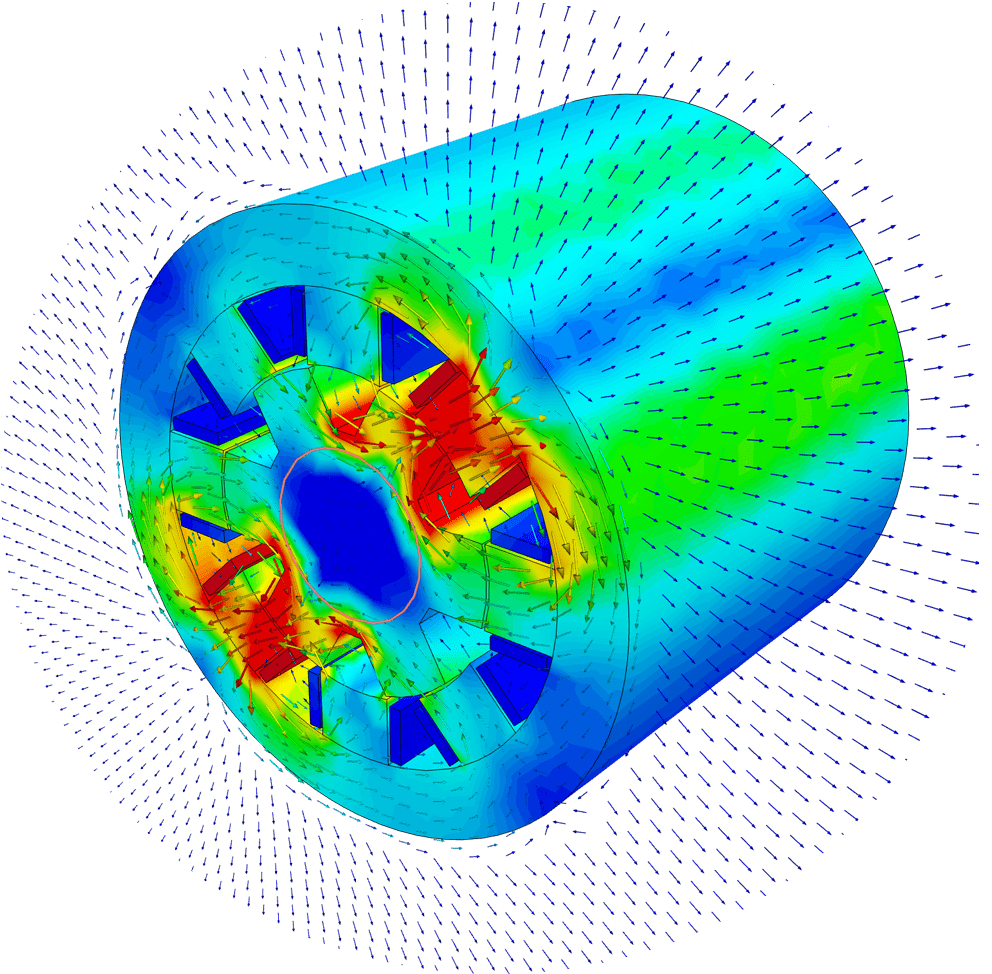
Magnetostatics, time-harmonic magnetics, and more →
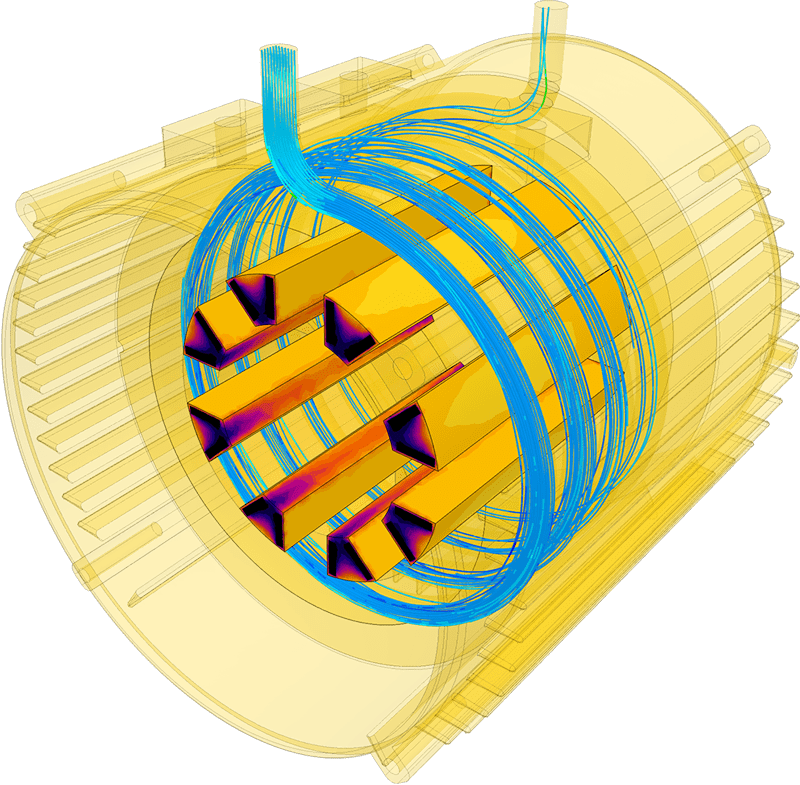
Coupled thermo-mechanical analyses, conjugate heat transfer, and more
Access open source, proprietary and 3rd party solvers with direct CAD and PLM connectivity.
Automated large-scale simulations producing high-fidelity physics data, stored centrally in the cloud.
Customize pre-trained AI models or build your own domain-specific variants, securely managed in the cloud.
AI & physics models blending neural network inference with first-principle solvers. Speed, precision, and explainability assured with architectures like NVIDIA’s PhysicsNeMo & DoMINO.
Secure, scalable APIs delivering AI-native simulation results to where your engineers already work.
Subscription Plans Adapted to Your Needs
Free for testing & learning
For higher fidelity simulation work
For team collaboration
For broad simulation roll-outs
Sign up for SimScale
and start simulating now