The simulation domain for a fluid dynamics simulation is the region occupied by the fluid (gas or liquid). However, in many cases, the original CAD model will initially not contain the fluid volume.
In such cases you can extract the fluid region, using the Flow volume extraction feature within SimScale’s in-place CAD Edit tool. We call this process Fluid Volume Extraction.
To illustrate the objective further, see the basic use case of a flow simulation through a pipe below.
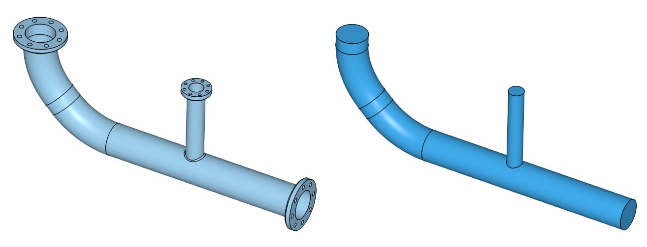
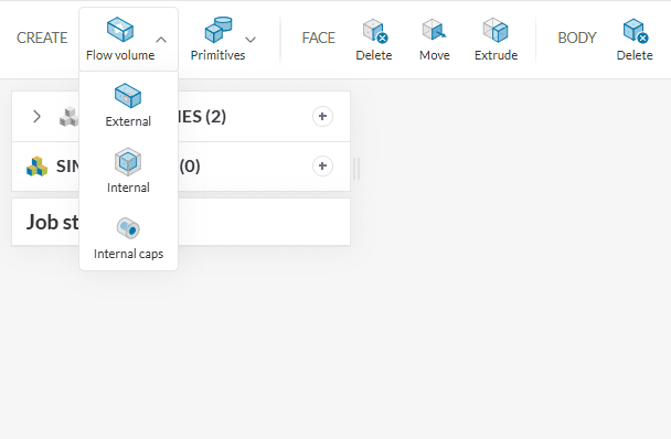
The two main flow volume extraction modes available within SimScale are:
- Internal Flow Volume
- External Flow Volume
Depending on your geometry, you may use one of two modes to extract the fluid volume. Below are examples for each type.
Did you know?
The third flow volume operation, Internal caps, is specific to conjugate heat transfer IBM simulations. Visit this page for more details.
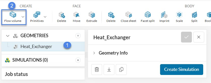
1. Internal Flow Volume
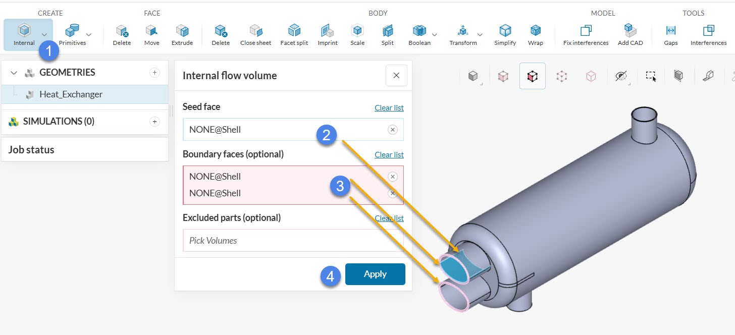
This operation generates an internal flow volume. For instance, the example below shows how to generate the internal flow volume of the heat exchanger from this tutorial. The heat exchanger has two openings for each fluid. Extract one of the flow volumes as follows:
- Select an ‘Internal‘ flow volume operation
- Select one internal Seed face (blue)
- Select the Boundary faces that lie between the external environment and the internal (highlighted in pink)
- If your geometry contains advanced concepts, such as porous media and momentum sources, assign them to Excluded parts. If not, leave this definition empty
- Hit ‘Apply’ to run the operation
This will result in a geometry that contains both the fluid volume and the outer wall geometry as two separate parts. However, for a simple fluid flow simulation, you need only a single fluid volume. Keep the outer wall geometry (solid body) only in case of a conjugate heat transfer simulation, in which heat transfer between the solid parts and the fluid domain is simulated.
If you are going to perform a single region analysis like incompressible, compressible, or convective heat transfer, you need to delete the solid body as follows:
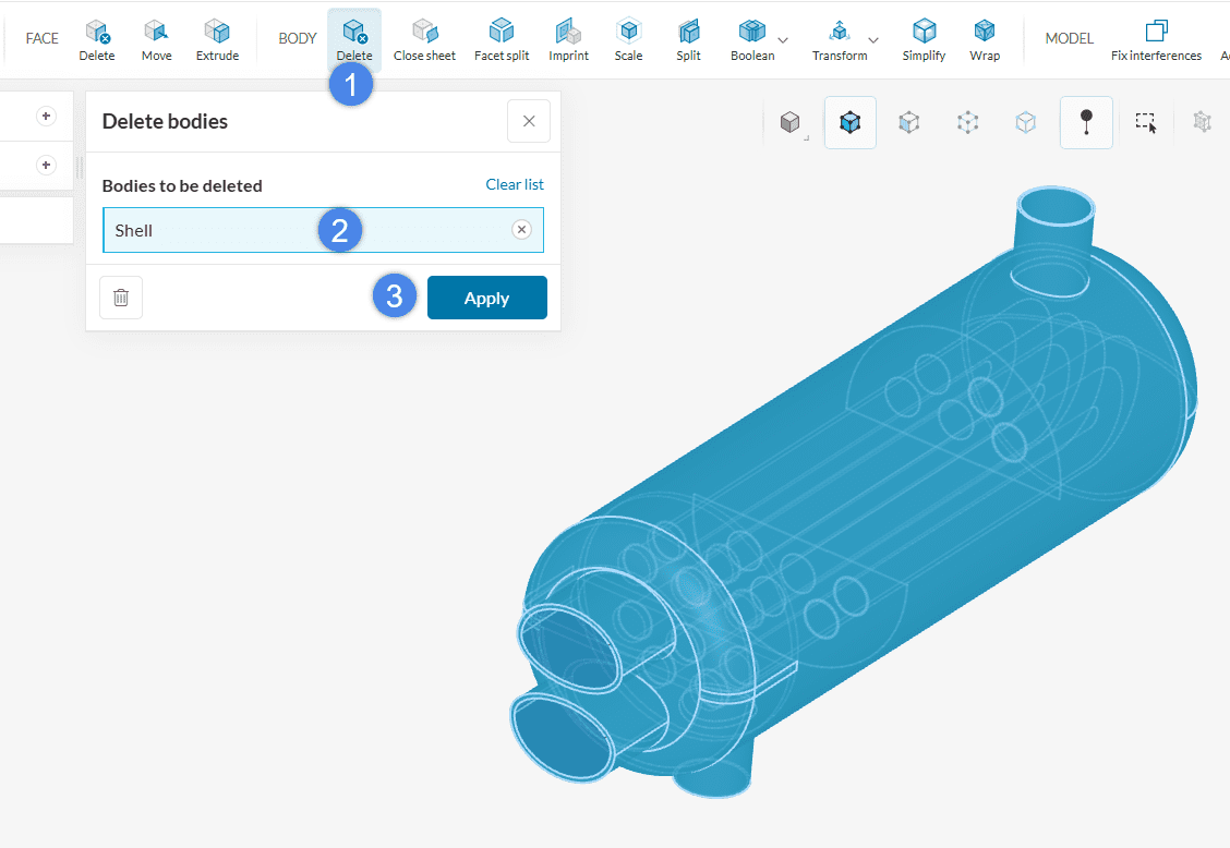
- Choose the ‘Delete’ operation under BODY
- Pick the solid volume that needs to be removed. In this example, it is the Shell of the heat exchanger
- Hit ‘Apply’
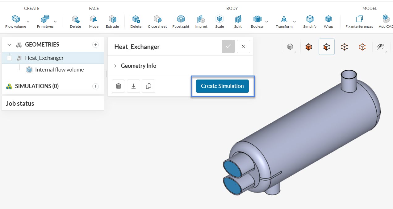
After all the operations are concluded, the geoemtry is ready and a simulation can be created.
Note that the definition of boundary faces is optional for internal flow volume operations. This is because some CAD models do not have any openings, leading to no boundary faces.
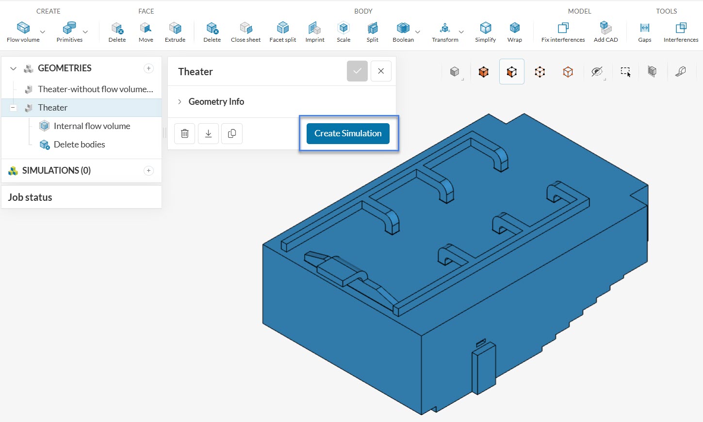
In the following image, you see the walls and ducting system of the theatre model highlighted in this tutorial. This theater room does not have any openings on the walls or duct system.
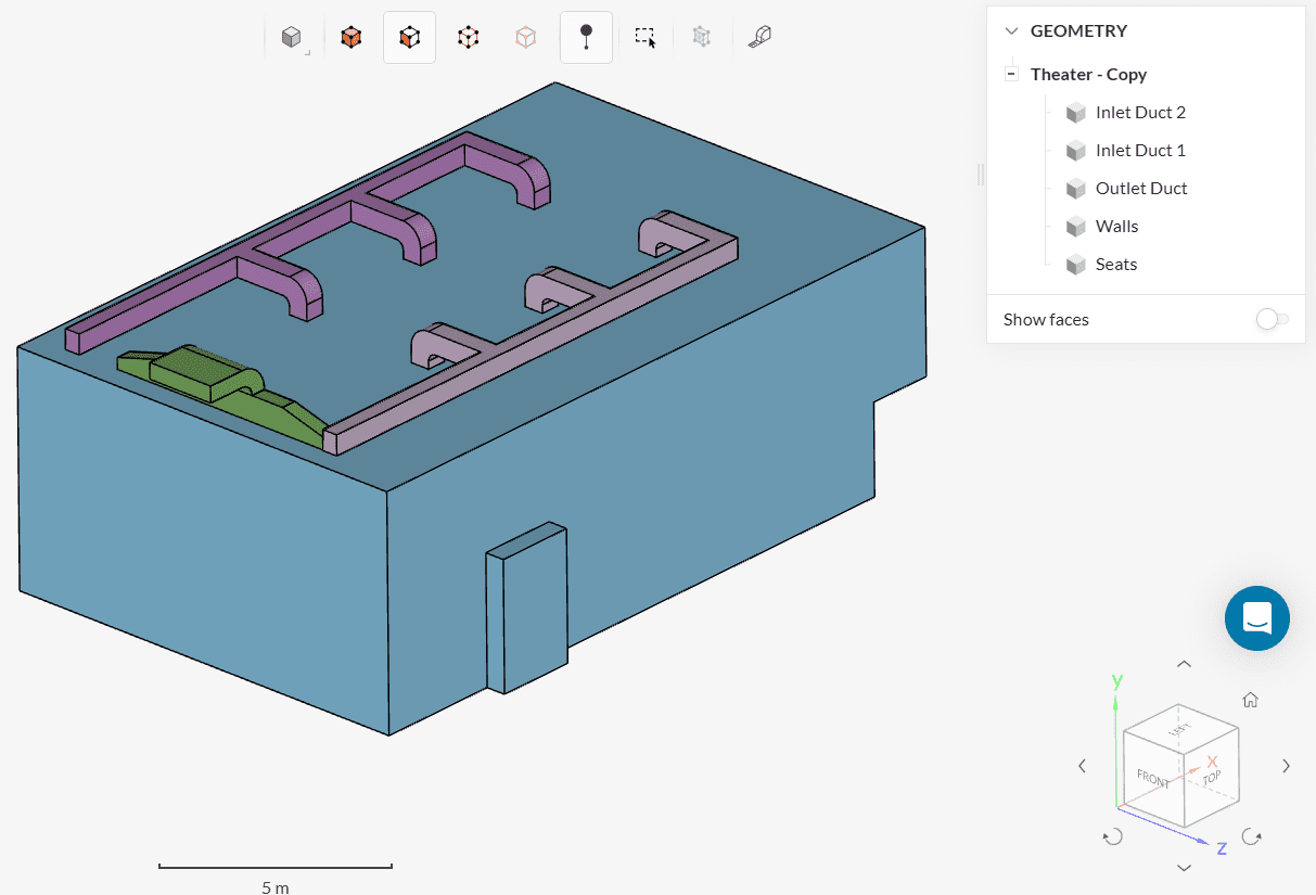
If this is the case, the only mandatory definition for an internal flow volume creation is a seed face. By hiding some of the external faces of the theater you will be able to select a seed face on the inside of the model.
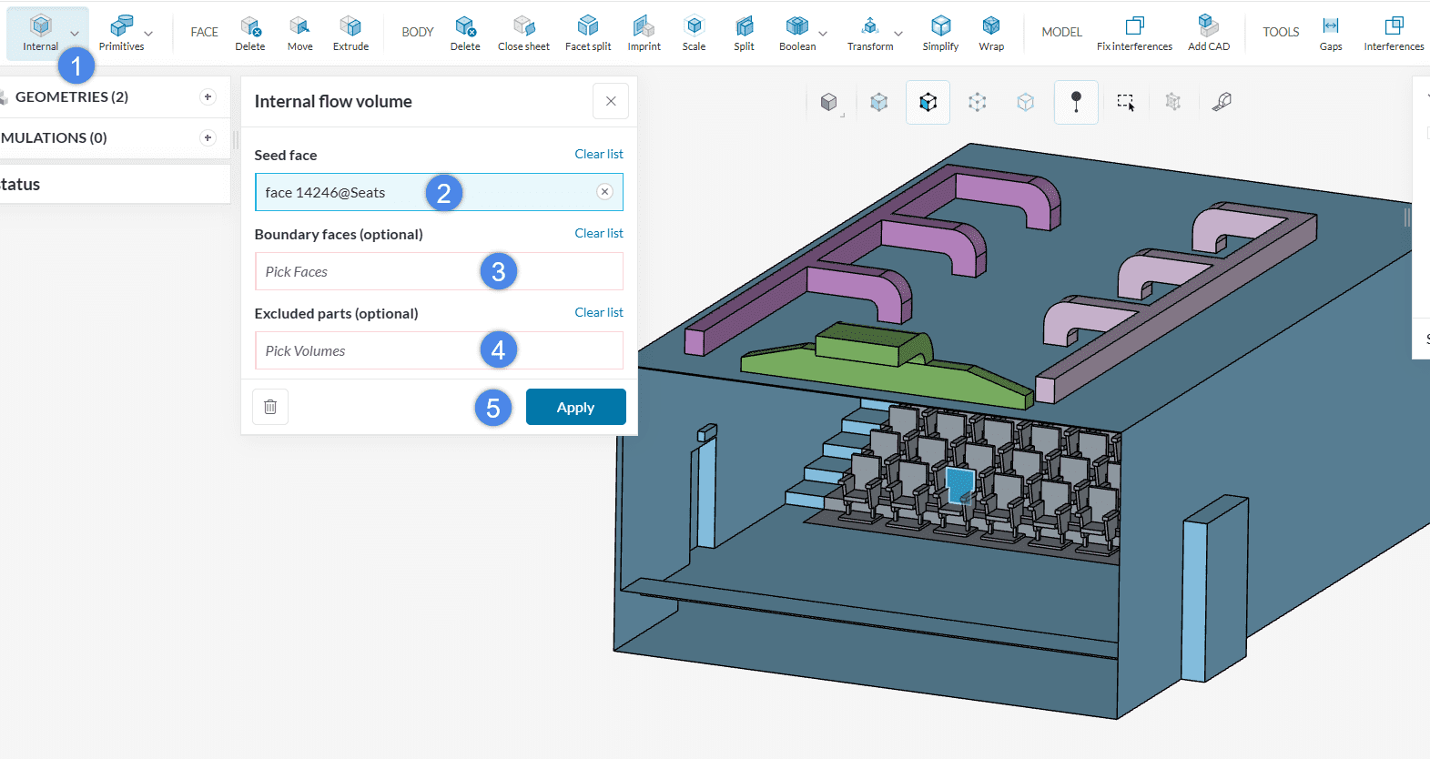
- Create an ‘Internal‘ flow volume operation
- Hide some external faces of the geometry and select one internal Seed face (blue)
- Leave the Boundary faces empty
- In case there are cell zones in your model, assign them to Excluded parts. If not, leave it empty.
- Hit ‘Apply’ to run the operation
After the flow volume extraction, you can delete the solid bodies and create a convective heat transfer analysis by clicking on Create Simulation.
2. External Flow Volume
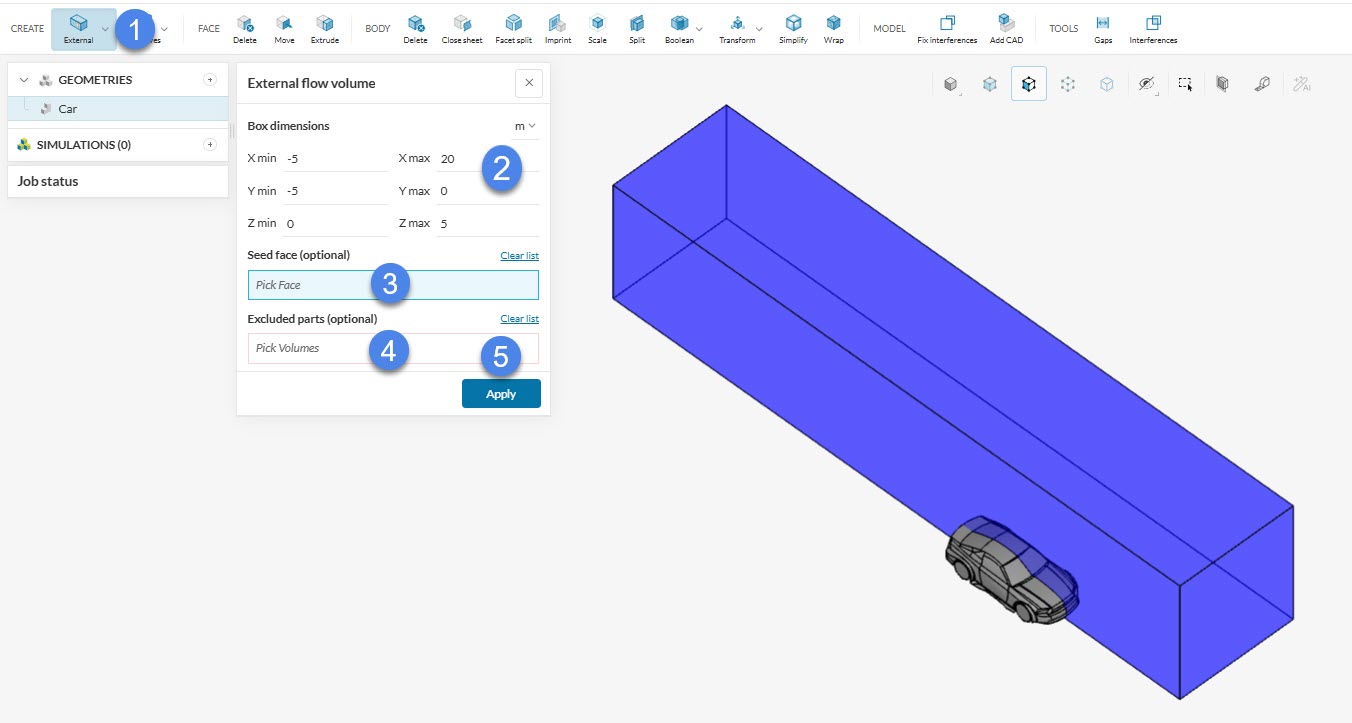
Above all, this option is often suitable for external flow problems. First, you need to size the external flow volume, and then run the operation. For instance, the example below shows how to generate a half-symmetrical air domain for the car geometry from this tutorial.
- After entering the CAD editing tool, select an ‘External‘ flow volume operation
- Define the External flow volume size by adjusting the minimum and maximum coordinates of the flow domain box
- The seed face definition is optional. If you leave this field blank, SimScale assumes that you are interested in creating a flow region external to the CAD model
- In case there are cell zones in your model, assign them to Excluded parts. If not, leave it empty
- Hit ‘Apply’ to run the operation
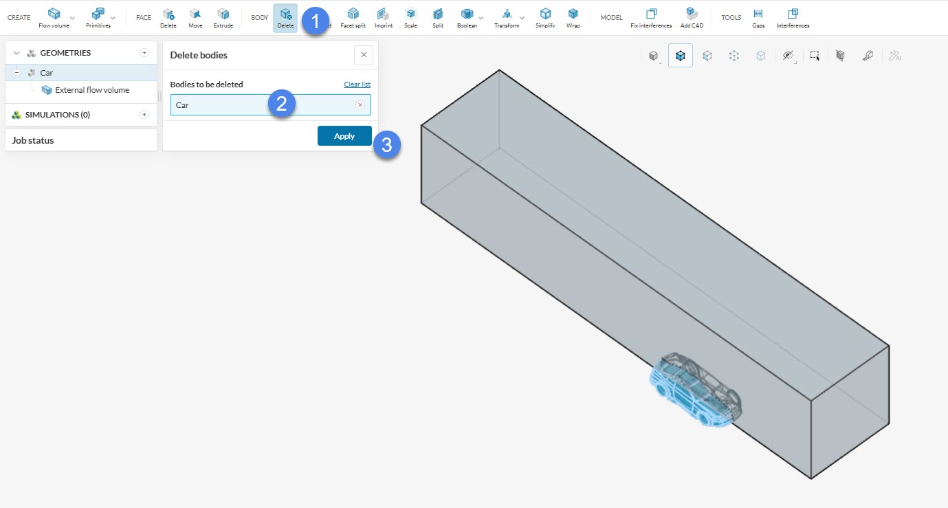
In addition, delete the solid parts to be able to use the model in an analysis type that requires a single fluid region:
- Pick the ‘Delete’ operation under BODY
- Select the solid parts
- Hit ‘Apply’
When creating the external flow domain, pay attention to the box size. The size of the flow domain box should be large enough that the turbulent wake behind the model as well as the pressure region in front of the model does not reach the boundaries of the box. On the other hand, a large domain will likely increase the simulation expenses. Therefore, use your engineering judgment and/or best practices to size the flow domain.
Running into errors
If the above steps are not followed properly you may run into errors. The possible reasons for these errors are elaborated here.
Note
If none of the above suggestions solve your problem, then please post the issue on our forum or contact us.


