This article covers the top reasons why imprint, internal and external flow volume extraction CAD Mode operations fail.
Before we start, it is advised to visit the documentation page on CAD preparation and upload. In addition, please visit the following knowledge base article to find out how to find CAD faults.
Common CAD Faults
CAD faults, in general, will most likely cause geometry operations to fail. Therefore, you should make sure that before uploading the model to the platform, it does not have any CAD faults. The most common CAD faults are:
- Small features/faces
- Inexact edges
- Overlapping faces/solids
- Sliver faces
- Knife edges/vertices
- Discontinuous faces/edges
- Bad faces
- sheet/surface elements
- Overlapping solids (interference)
To check the CAD faults above, many CAD software have features to detect the common CAD errors.
Following are some geometry operations you will find in SimScale CAD Mode.
1. Imprint
Always use the imprint operation if you have a model with multiple parts.
- Imprint operation fails due to the interference between parts.
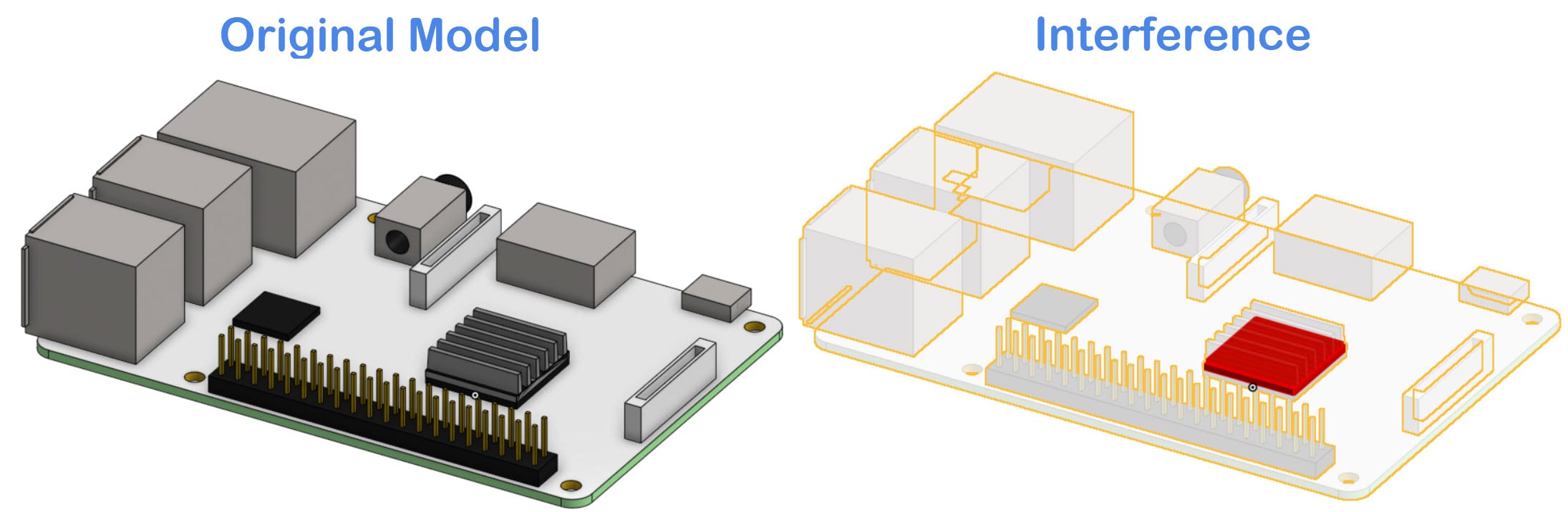
To resolve interference faults, first, you need to perform an interference check on the CAD model. Our CAD mode has this facility to detect and automatically fix interferences. For manual fixing, once you detect an overlap, you can subtract the body from the other one to remove the overlapping region. Alternatively, you can merge the two parts into one if this is suitable for your case. Check our Boolean operations integrated for this purpose.
In conclusion, imprint operation will work on an interference-free CAD model.
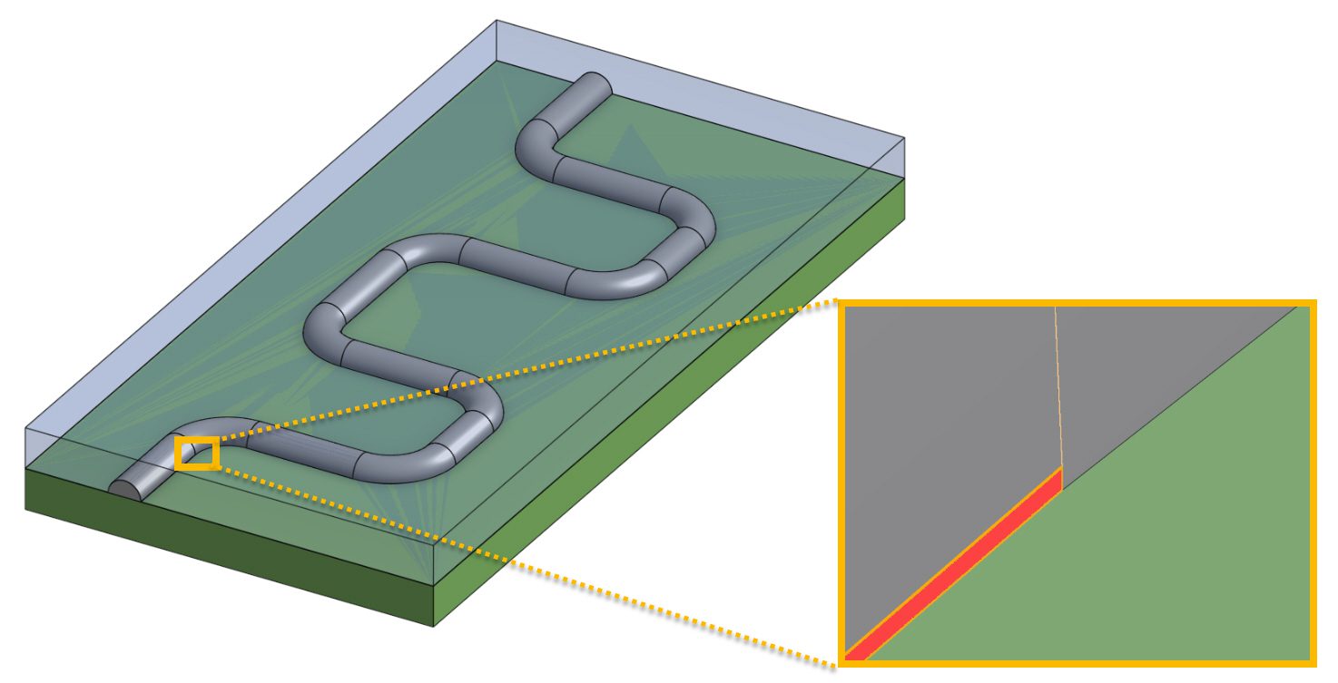
- Imprint operation fails if there is a small face or a sliver face on one of the contact faces. Clean the small and sliver faces in CAD Mode or on your CAD software, before uploading the model to the SimScale platform. In the following picture, you see a PCB board (green), covered by a resin layer (semi-transparent blue). The cooling is performed by a cooling pipe (grey). Imprint operation is necessary to capture the contacts between each part and execute a CHT analysis.
2. Flow Volume Extraction
To learn more about the flow volume extraction geometry operation, visit this Knowledge Base article.
2.1 Internal Flow Volume
If your model has openings and you would like to create a flow volume inside, use this geometry operation. This operation possibly fails because of the following CAD faults:
- Interference between surfaces
- Boundary faces are not parallel
Boundary Faces
The following picture is an example of the boundary faces not being parallel:
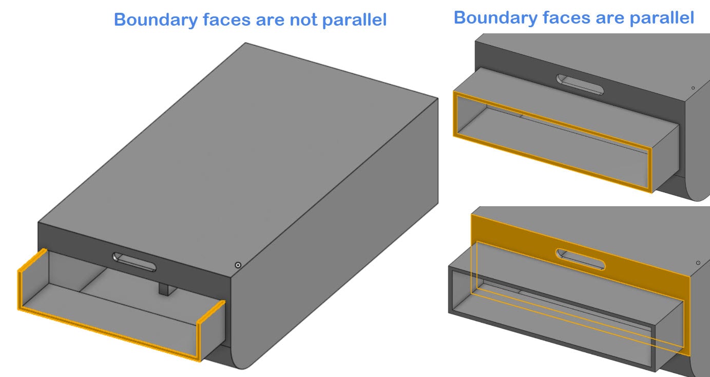
In this case, you will need to make sure that all the faces that are facing the environment outside of your model are parallel. The picture on the left shows that the two faces on the top are not parallel with the two faces on the side. The picture on the right shows an example of a parallel boundary face.
- Boundary faces are not completely closing the openings of the cross-section
The following example shows how the boundary faces at the opening should be created:
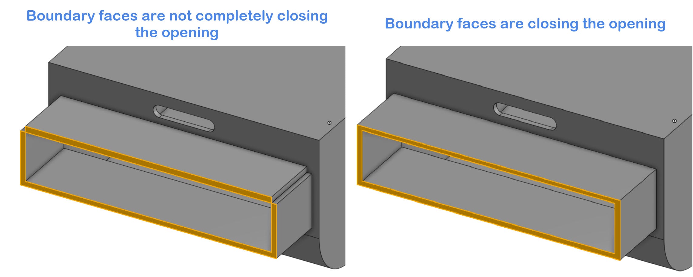
You will also need to ensure that the boundary faces do not have any openings. This can be seen in the picture on the right where the top and side faces do not meet on the four corners. You can solve this by changing the four faces into one face.
Contact Boundaries
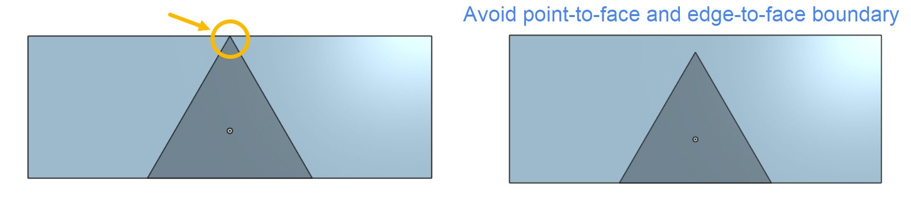
- An internal part has an edge-to-face or point-to-face contact with the boundaries of the fluid volume
You see an edge-to-face contact example in the following picture:
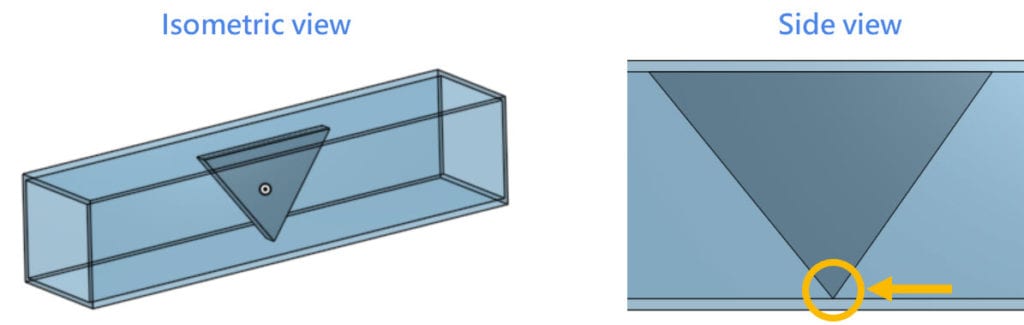
Avoid any point-to-face or edge-to-face contact between the internal parts and the boundaries of the fluid volume. One way to avoid this issue is to trim the sharp edges and/or corners, in contact with the walls.
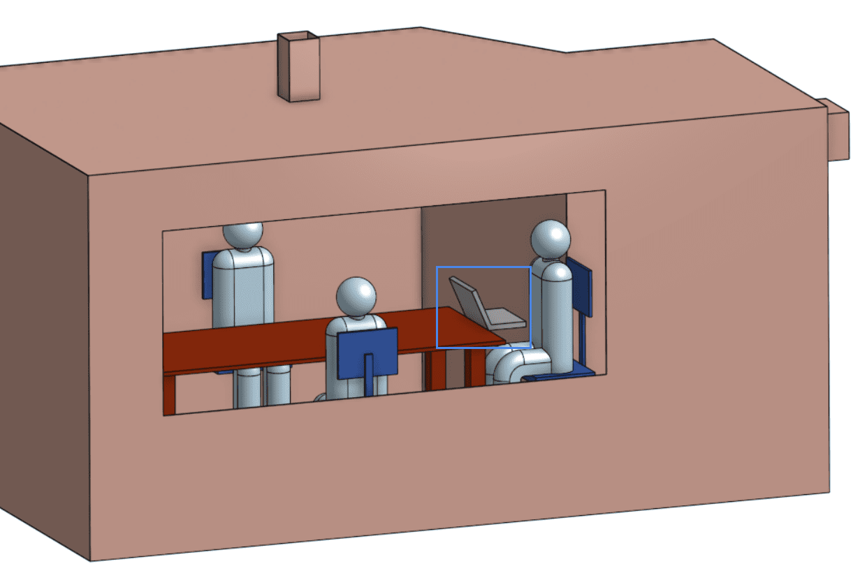
- Two internal parts have an edge-to-edge contact: this happens when two parts share a single edge, and there are no face-to-face contacts. For example, in the CAD model below, there is an edge-to-edge contact between the laptop and the table:
From a side view, the edge-to-edge contact is clear. One way to solve the problem is to generate a face-to-face contact by translating/extending one of the volumes:
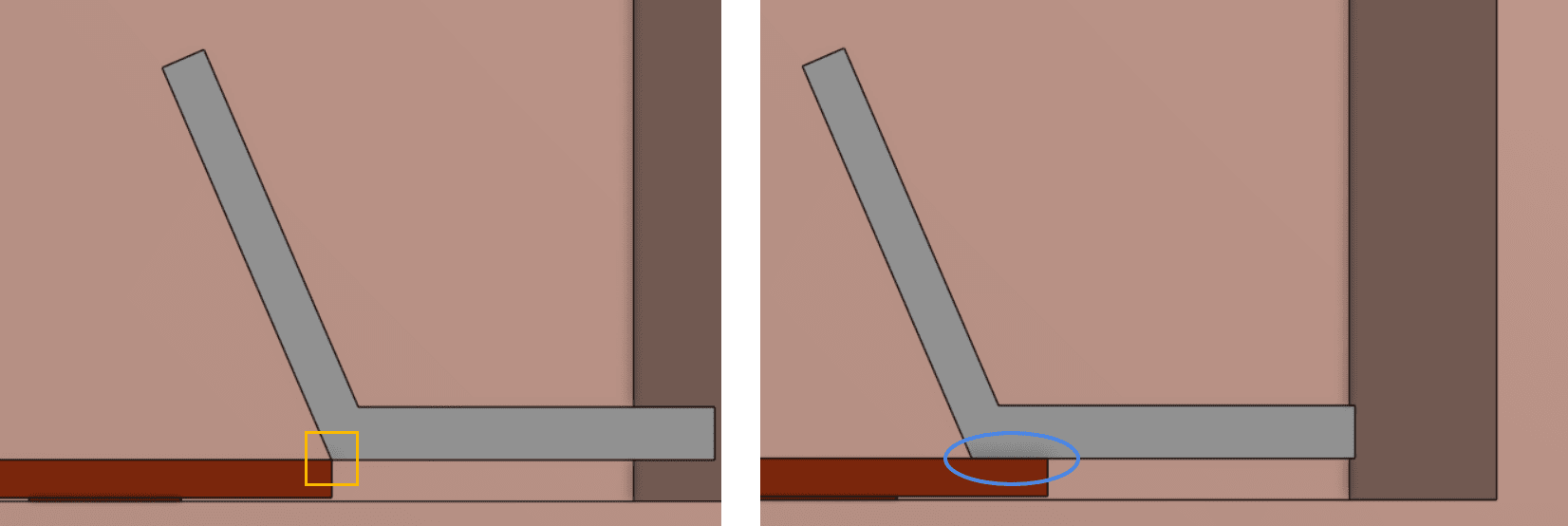
Another possibility is to move the laptop to the right, preventing the edge-to-edge contact from occurring.
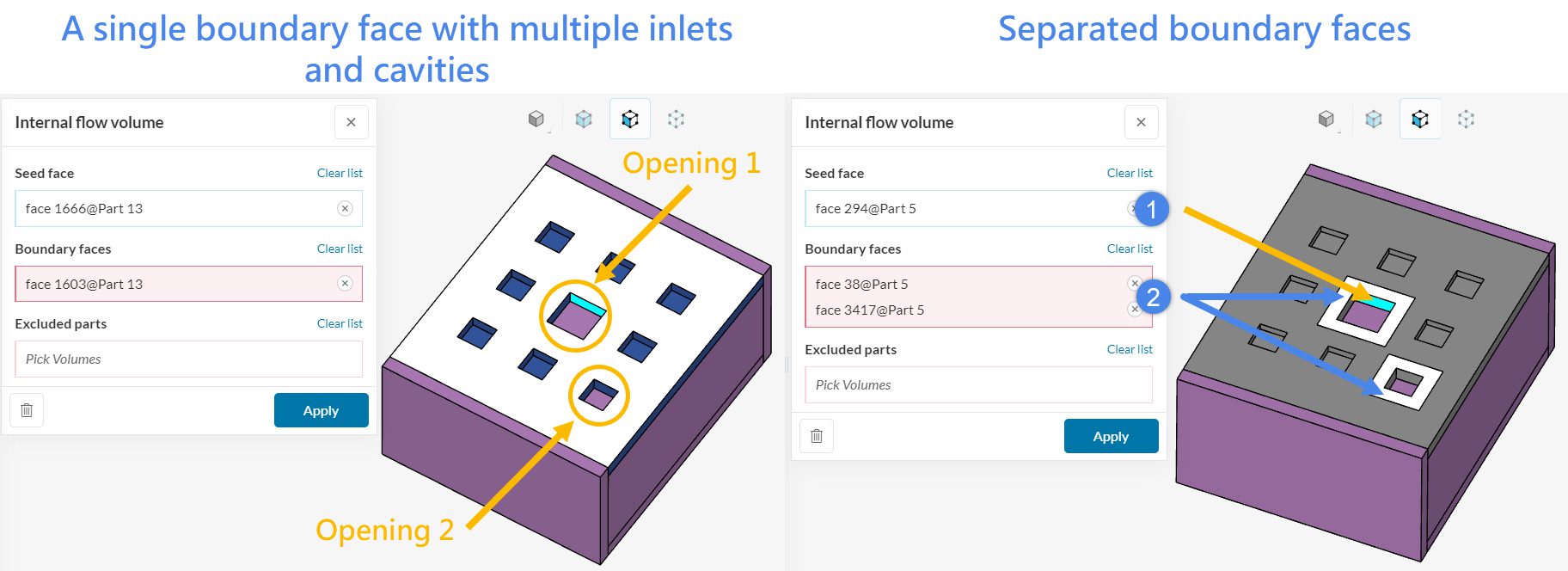
- A boundary face is shared by multiple openings and cavities
If multiple openings and cavities share the same boundary face, under some exceptional cases, internal flow volume extraction might fail. In this case, it is recommended to separate the boundary faces of the inlets.
In the next example, there are two openings and seven cavities on the highlighted face. The flow volume will be generated inside the box, not in the cavities. Therefore, we had to separate (isolate) the boundary faces of the openings from the main face. To clarify, this operation needs to be done in CAD mode.
2.2 External Flow Volume
This operation possibly fails because of the following CAD faults:
- Interference between surfaces
- An internal part has an edge-to-face or a point-to-face contact with the boundaries of the fluid volume
Further Tips
The following points are essential:
- Firstly, avoid sheet/surface elements. In other words, the CAD model should only consist of solid parts.
- Secondly, avoid overlapping solids (unless they represent cell zones).
The following points are not essential, but we strongly recommend to perform a cost-effective simulation experience:
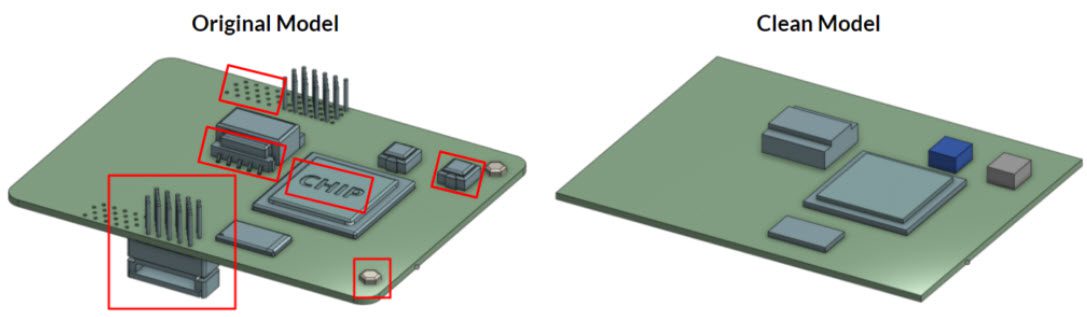
- Model only the essential parts. In other words, remove unnecessary features or components, such as small nuts, bolts, pins, etc.
- Fill leftover holes and gaps.
Note
If none of the above suggestions solved your problem, then please post the issue on our forum or contact us.


