A Seed face occurs in the context of flow volume extractions operations. If you are not yet familiar with the extraction of flow volume using SimScale, you can look it up here.
Seed Face Selection
In a flow volume extraction operation, the algorithm doesn’t know where the flow region should be created, as oftentimes there will be multiple options. The Seed face serves exactly this purpose: it indicates where to create the flow region, by acting as the source face for the flow volume.
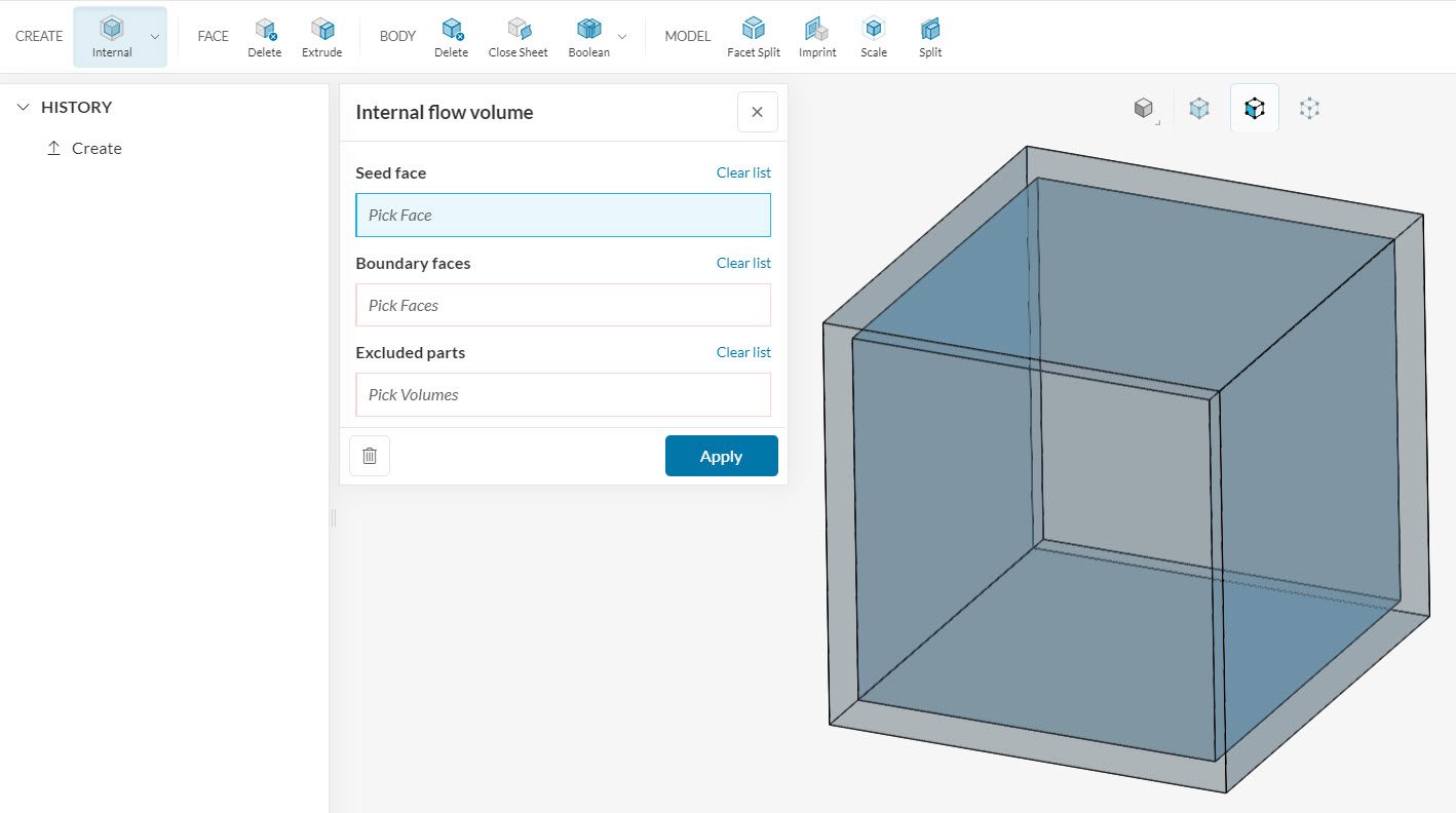
Let’s say that we have a cube that is hollow inside. We can create a fluid volume to fill the hollow region, or we can create a fluid volume external to the cube. Depending on the configuration of the flow volume extraction operation, both internal and external volumes can be created in SimScale.
There are two ground rules for the seed face selection:
- It must be in contact with the flow volume that you wish to create
- If the geometry has open boundaries, the seed face must be connected to the Boundary faces. For instance, we cannot select a face from a floating object
We will show some examples below, using operations available in the CAD Mode environment.
Internal Flow Volume
When the geometry has open boundaries, the best choice for a seed face is an internal face that is adjacent to one of the boundaries. For example, in Figure 2, we have a meeting room with a single open boundary, representing a window.
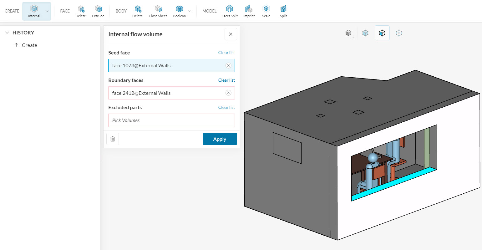
Note that multiple seed faces are valid choices in the case above. For simplicity, the easiest choice is to select a face that is both adjacent to the boundary face and in contact with the flow volume that will be created.
For geometries without boundary faces, you can simply select any of the internal faces, which will be in contact with the flow region. Taking the same cube geometry from Figure 1, if we want to create a fluid region internal to the cube, the necessary steps are in Figure 3:
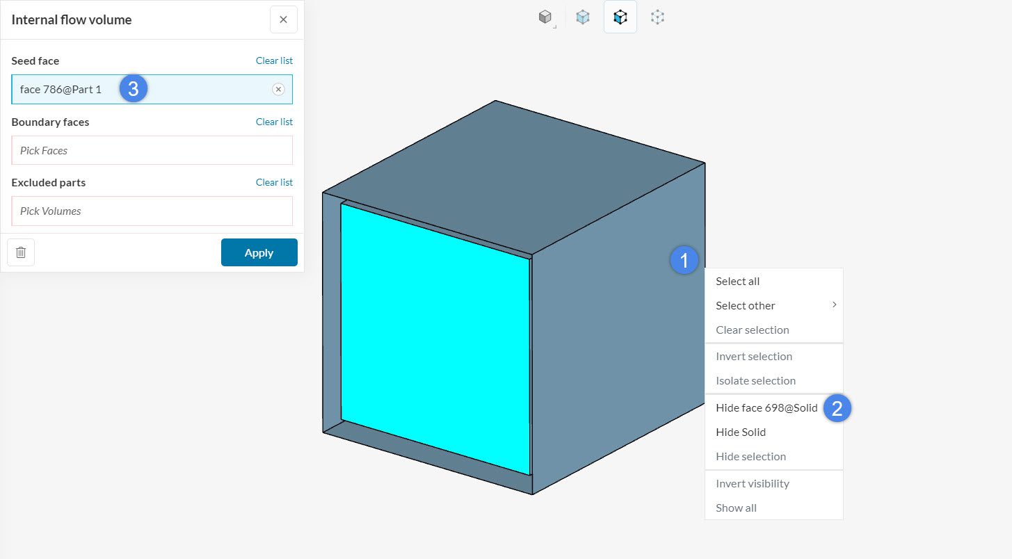
- Right-click on an external face
- Select the hide face option
- Assign one of the internal walls, in contact with the internal void, as a seed for the flow volume
Note
Please note that no boundary faces are defined for fully closed volumes.
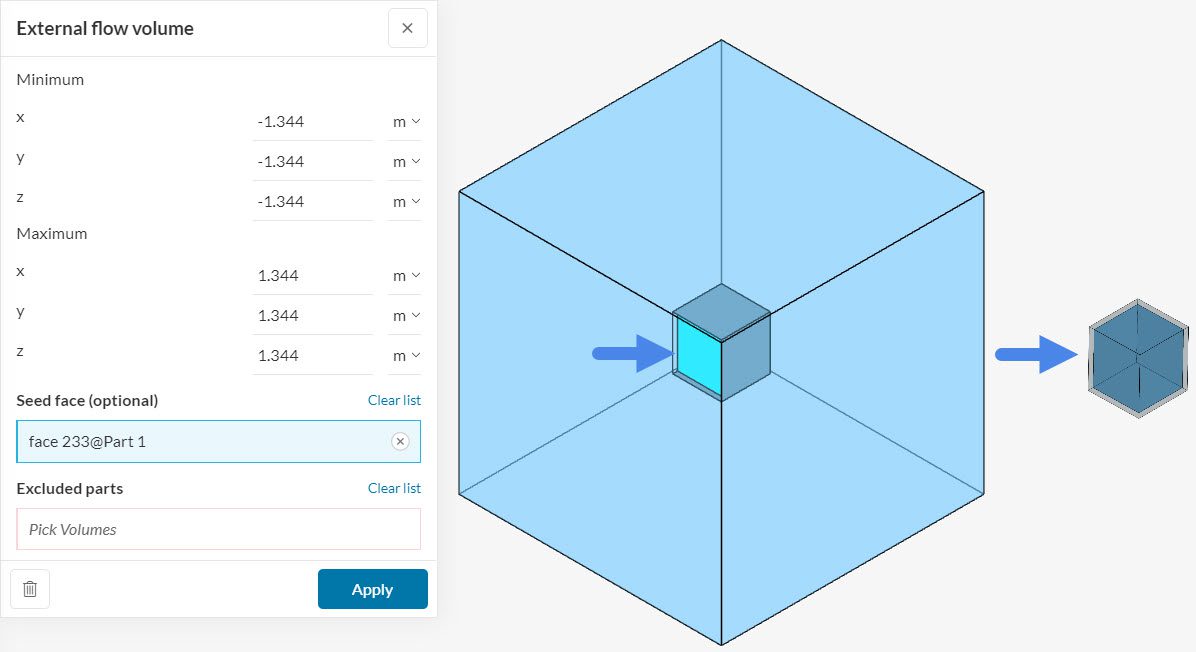
External Flow Volume
For External flow volume operations, the Seed face definition is always optional. In case the user does not assign any face, the algorithm will automatically create an external flow volume.
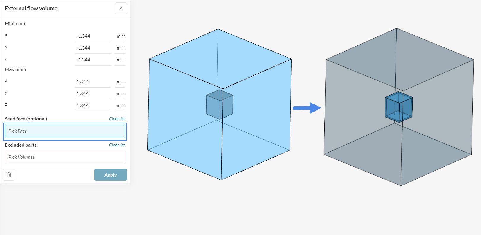
As the image above shows, the default flow region is always external to the geometry. Note that if we define a seed face internal to the cube (as in Figure 3), we are going to end up with the internal flow region instead: