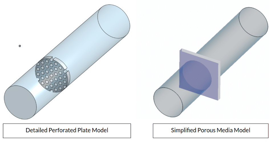
Perforated plates are plates with patterns of holes, slots, or decorative shapes. They have a wide area of usage in industrial applications, such as filters, silencers, radiator grilles, ventilation, or separator plates.
If a perforated plate needs to be involved in the model, and if the thickness of the plate is bigger than the hole diameter, using porous media feature might be computationally cheaper than actually modeling the plate itself.
How to Use Porous Media Feature?
Under Advanced Concepts, choose one of the Porous media models:
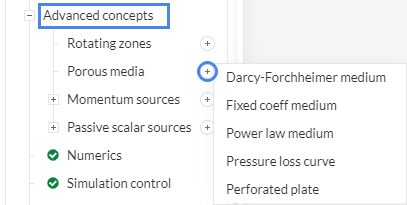
Although any of the above listed porous media models can be used, this article mainly focuses on the usage of the Darcy-Forchheimer model due to its popularity. To learn about other models please visit our standard documentation on porous media :
Darcy-Forchheimer Medium
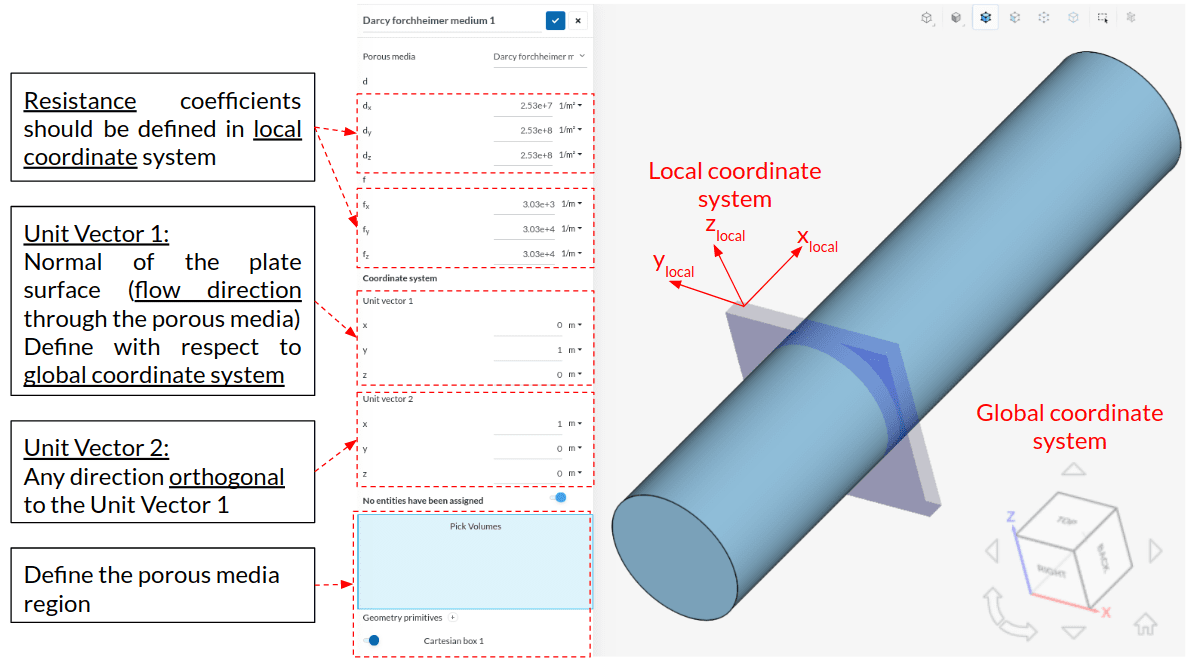
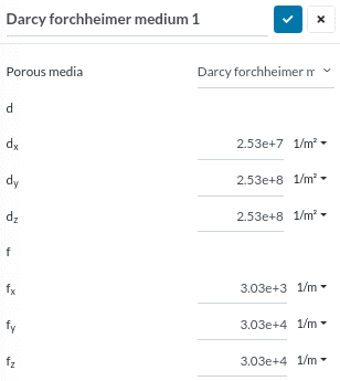
Selecting this model will lead you to the settings panel as shown in Figure 3.
- Assign the Darcy (d) and Forchheimer (f) resistance coefficients with respect to local coordinates.
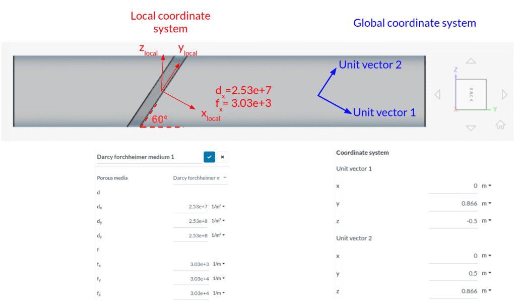
- Assign Unit vector 1 and Unit vector 2 with respect to global coordinates.
- Assign the porous media region:
- If you created the region in the CAD model itself then pick the volume region.
- If not, then create a Cartesian box using Geometry primitives and select the box.
While the sponge-like structures permit the flow evenly in every direction (isotropic), perforated plates transmit the flow in a particular direction (anisotropic). To simulate an isotropic structure, dx, dy, dz and fx, fy, fz should respectively be the same. However, fluid will flow only in 1-direction in perforated plates. Therefore higher resistance should be added to the other 2 directions (as an example, multiply dy, dz and fy, fz by 10).
If you would like to learn how to predict Darcy and Forchheimer Coefficients for perforated plates, check the following pages
- Predict Darcy and Forchheimer coefficients, using experimental data
- Predict Darcy and Forchheimer coefficients, using empirical equations
How to Define Inclined Perforated Plate?
The following content discusses a case of an inclined perforated plate inside a pipe. Assuming the perforated plate has identical properties as the previous one, the same Darcy and Forchheimer coefficients can be applied.
In this example (inlet on left), Darcy and Forchheimer coefficients for the perforated plate are calculated as 2.53e+7 and 3.03e+3 respectively. Since coefficients d and f need to be defined in the local coordinate system, just assign the corresponding values to dx and fx. Flow won’t pass through the closed surfaces, therefore we need to add a higher resistance to the other two directions (2.53e+8 and 3.03e+4). These will be assigned to dy, dz, and fy, fz respectively.
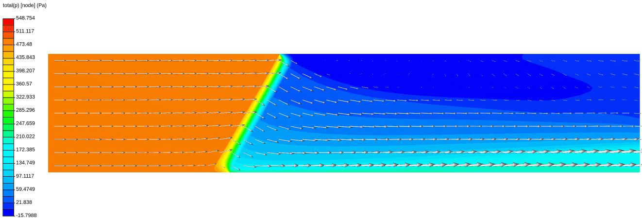
The following picture represents the pressure gradient on the cross-section of the pipe and perforated plate. Velocity vectors show how the flow is aligned through the perforated plate.