What is Aerodynamics?
Aerodynamics is the science of moving air and its impact on solid bodies placed in the flow field as an obstacle. Being a sub-field, most of the equations from fluid dynamics apply to aerodynamics as well, including all the governing equations, turbulence, boundary layer theory, and ideal gas assumption.
History of Aerodynamics
Although the wind had been widely used as a tool by humankind (windmills, sailboats) already, the beginning of the scientific study of aerodynamics only dates back to the seventeenth century. The dream of flight and a machine that is “lighter than air” was already present in ancient history. Very early attempts to describe flow quantities appear in the work of Aristotle and Archimedes; however, the scientific field “aerodynamics” does not appear in their notes.
The very first aerodynamicist was Sir Isaac Newton, who developed and described the theory of flow resistance, also known as drag. Further famous scientists such as Bernoulli, Euler, Navier, and Stokes gave a more precise and mathematically founded description of gas dynamics. The famous Navier-Stokes governing equations of fluid dynamics were born in 1800, however, this is also the most difficult model to solve.
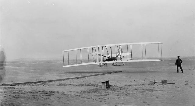
The desire for the flight was always the main driving force behind the development of the engineering field of aerodynamics. In the early 1800s, engineers and scientists studied the aerodynamic forces of flight. Terms like “drag”, “lift”, and “thrust” were born and the relationships between them were determined. In 1871, the first wind tunnel was built. Drag theories by engineers like Kirchhoff and Rayleigh were established. Otto Lilienthal was the first person to become successful with glider flights, and after all this research work, the Wright brothers flew for the first time with an engine-powered airplane in 1903.
But the study of aerodynamics around airfoils did not stop here. Lanchester, Kutta, Zhukovsky, and Prandtl developed theories to better describe flow circulation around wings. While the First and the Second World Wars boosted the development of aircraft and the science of aerodynamics, the next breakthrough happened in 1947, when the sound barrier was broken for the first time with a Bell X-1 rocket-powered aircraft. At this point, the understanding of subsonic and supersonic flows had matured, however, the evolution was still to continue. With the appearance of computers, the numerical calculation of the governing equations became possible. Computational Fluid Dynamics models and software started to appear on the horizon. Nowadays, CFD is utilized in almost every development process where airflow is involved and plays an important role.

Flow Classification and Equations
An aerodynamic flow field can be classified based on the following physical parameters: velocity, pressure, and temperature. Additionally, density and viscosity can be used as well although the velocity and pressure-based flow classifications are the most common.
Velocity-based Classification
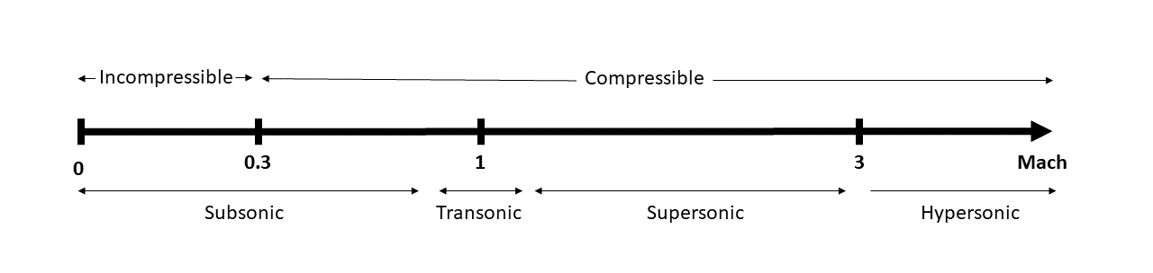
Subsonic
Subsonic flows are flow fields in which the air speed does not exceed the local speed of sound, which is \(M<1\). Typical examples are common ground vehicles like cars, trains, F1 cars, and sport airplanes. \(M\) represents the Mach number which is the flow velocity past a boundary. For more information about mach number, please read our article on incompressible flows.
Transonic
Transonic flows include both subsonic and supersonic flow regimes \(0.8<M<1.2\). Typically, commercial airplanes fly in this speed region. A supersonic flow zone appears when the otherwise subsonic fluid accelerates above sound speed due to surface curvatures (e.g. suction side of the wing).
Supersonic
Supersonic flows are defined as having velocities greater than the speed of sound everywhere in the domain (\(M>1\)). Military jets and gun bullets are good examples of supersonic flows.
Hypersonic
We could also include hypersonic flows, where the speed is much higher than the speed of sound. There is no accurate definition of this value (\(M>>1\)). Some hypersonic rocket-powered airplanes and spacecrafts can be mentioned as examples where the match number is 5 or more.
Density / Pressure-based Classification
Incompressible
Incompressible flow refers to a flow where the material (air) density remains constant. Under Mach 0.3 this is a good assumption for industrial flows and helps engineers simplify the simulation. Please note that an incompressible flow does not mean that the fluid has to be incompressible itself.
Compressible
A flow can be considered compressible if the density changes along a streamline. Generally, this is the case for subsonic flows above Mach 0.3. Transonic, supersonic, and hypersonic flows are all compressible.
Aerodynamic Quantities
As mentioned before, aerodynamics is the study of forces on a solid body placed in an airflow. In order to better describe and understand these effects as well as to be able to compare cases easier, one can use mathematical quantities. These parameters include drag, lift, moment, center of pressure, and pressure coefficient, to name a few important ones.
Drag
One of the most important quantities in aerodynamics is the resistance of the fluid, also known as drag or drag force. This force is acting opposite to the motion of the solid body relative to the air thus causing losses. This drag force depends on the relative velocity as well as on the shape of the solid body. The drag force can be computed using the following equation:
$$ F_{d}={\frac {1}{2}}\rho \,u^{2}\,C_{D}\,A \tag{1}$$
where
- \({\displaystyle F_{d}}\) is the drag force,
- \({\displaystyle \rho }\) is the density of the fluid,
- \({\displaystyle v}\) is the speed of the object relative to the fluid,
- \({\displaystyle A}\) is the cross-sectional area, and
- \({\displaystyle C_{D}}\) is the drag coefficient which is dependent on the shape of the object and the Reynolds number.
Lift
Another component of the resulting force on a solid body is called lift or lift force. This component is perpendicular to the oncoming flow direction. The term “lift” comes from the aeronautics field, where it is an important quantity that makes flying actually possible for objects heavier than air. But lift force is generated in propellers, helicopter rotors and even on car bodies and wind turbines too. Usually, an asymmetric body or a symmetric body with an angle of attack produces lift force. Lift can be determined by the following equation:
$$ {\displaystyle L={\frac {1}{2}}\rho v^{2}SC_{L}} \tag{2}$$
where
- \(L\) is lift force,
- \(ρ\) is air density,
- \(v\) is speed,
- \(S\) is the projected area, and
- \({\displaystyle C_{L}}\) is the lift coefficient
Moment
Aerodynamic moment or torque is produced by the aerodynamic force on a body (wing, car on any solid) causing it to rotate in the flow field. The rotation happens when this turning force is acting outside the center of pressure or the aerodynamic center.
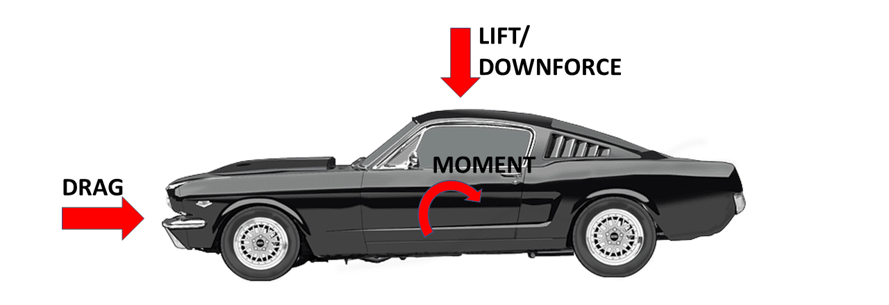
If you imagine the air stream going from the front of the car over the engine hood, you can imagine that the air wants to lift the car at about the point where the headlights are. This is where the moment illustrated in Figure 3 is generated.
Center of Pressure
The Center of Pressure (CP) is a point where the force generated by the total sum of the surface pressure acts. This force can be calculated as the surface integral of the pressure field and can be used to calculate the stability of an aerodynamic body. For example, when analyzing the aerodynamics of a bullet shot from a gun, the distance between the CP and the center of gravity can create a rotating moment thus making the projectile less accurate. Easily speaking you can imagine the center of pressure as something like the center of gravity where the average weight of an object is.
The center of gravity of a hammer, for example, is far away from the middle because the handle is usually a lot lighter than the head. The same goes for aerodynamics. The center of pressure is the point where the average aerodynamic forces drag and lift/downforce exert. The center of pressure allows engineers to balance the lift of an aircraft.
Forces on an Airplane
For an airplane flying, we can see the forces acting on the airplane (weight and drag) and generated by the airplane (thrust and lift) as represented by the following figure.
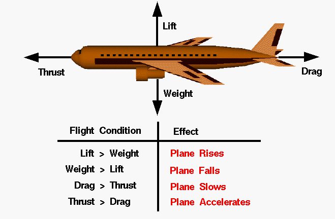
Thrust
The airplane needs a push to move forward. This is provided by the propeller or the jet engines in the form of thrust. The gases from the burnt fuel quickly expand and are thrown away from the exhaust pushing the plane forward. The thrust force should be more than drag for the plane to keep accelerating.
Weight
The weight of the airplane acts in the downward direction and needs to be balanced by the lift force for the plane to stay in the air. Higher the weight, higher will the lift required. In cars, the net lift force should act downwards to provide enough contact between the wheel and the ground. Spoilers in cars are a great example of net downward lift which increases traction and braking capabilities by increasing the downward force on the back of the car
Pressure Coefficient
One of the most widely used non-dimensional numbers to visualize pressure on the surface of the aerodynamic body is the pressure coefficient \(C_p\). This quantity describes the relative pressures in an incompressible flow and can be calculated as
$$ C_p={p-p_{\infty}\over {\frac{1}{2}}\rho_{\infty}V_{\infty}^{2}}={p-p_{\infty}\over p_{0}-p_{\infty}} \tag{3}$$
where
- \(p\) is the static pressure at the location where pressure coefficient is calculated,
- \(p_{\infty }\) is the static pressure in the free stream,
- \(p_{0}\) is the total pressure in the free stream,
- \(\rho _{\infty }\) is the free stream fluid density,
- \(V_{\infty }\) is the free stream velocity of the fluid, or the velocity of the body through the fluid.
It can be seen that using \(C_p\), different scenarios of flow velocities, pressures and densities can be compared for the same geometry. \(C_p\) visualization is broadly used in the automotive or aircraft industry where different study concepts are compared to each other in a virtual wind tunnel.
Boundary Layer
In aerodynamics, the description, measurement, and simulation of a near wall velocity and other quantities are always a challenge. As the flow decelerates rapidly near a solid wall, the viscosity effects become significant in a thin region also known as the boundary layer. Boundary layers are classified into two main groups: laminar boundary layers at low Reynolds numbers and turbulent boundary layers at high Reynolds numbers.
Turbulence
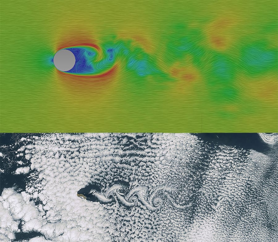
Turbulence plays a significant role in aerodynamics. Turbulence is a chaotic, irregular phenomenon observed in less viscous fluids. In general, unsteady vortices appear in many sizes in the flow field and interact with each other and the solid body which usually generates them. Turbulence can be “good” when, for example, one wants to generate thinner boundary layers and “bad”, when it leads to large separations and therefore increased drag and losses.
Capturing the turbulence accurately has troubled the CFD community for years yet there are several ways using which one can simulate them effectively to achieve accurate aerodynamic results. This can be done by either modeling it (RANS) or resolving the eddies (LES, DES). What is turbulent flow? explains this phenomenon in detail.
Would you like to perform aerodynamic analysis?
Within few seconds you can create a SimScale account and access tutorials, validation cases, public projects, etc. on aerodynamics and also receive support from our forum and application engineers.
Give SimScale a try!
Applications of Aerodynamics
If there’s air then there’s aerodynamics. There are countless applications that can be associated with aerodynamics. Almost all the transportation devices and big structures we have around experience airflow in and around them and an accurate airflow analysis will result in the efficient design of these entities. Following are some of the many areas where aerodynamics analysis is paramount:
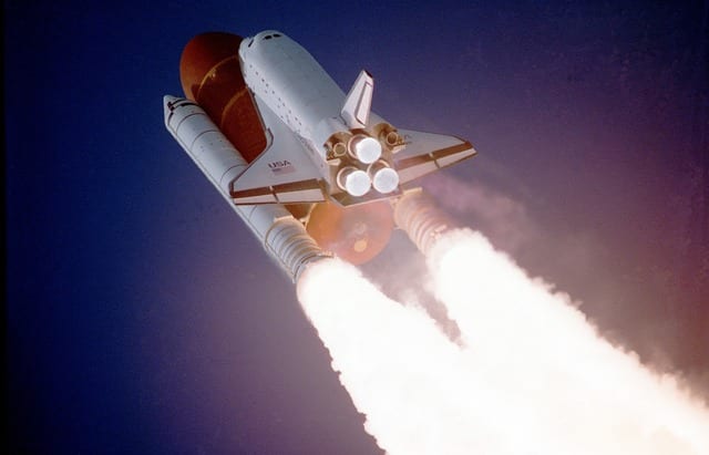
Aerospace
As described in the History above, the first studies of aerodynamics appeared with the desire of flight. Later on, the aerospace industry and its continuous research and development on aircraft required many mathematical models, measurement devices, wind tunnels and so on, all designed to understand aerodynamics better. Nowadays it is a key field of study to reduce emissions, reduce environmental noise and improve human comfort. The terms lift, drag, and moment commonly appear in the design process of an aircraft.
Automotive
The automotive industry is very competitive these days. With the desire to build environmentally friendly or even zero-emission vehicles, the reduction of drag is a key aspect of the development process. Brake cooling and HVAC airflow can also be mentioned here as some of the main topics of aerodynamics. The importance of lift force appears mostly when studying stability and when designing race vehicles.
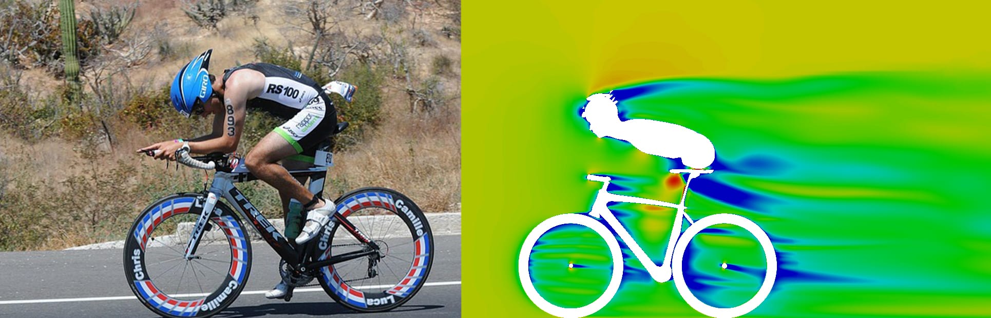
Sports
With the continuous improvement of performance in sports, the aerodynamics of race bikes, swimmers, Formula 1 cars is becoming more and more important. In a competition, where even milliseconds count, the reduction of the drag by 0.1% can distinguish the winner from the others. Modern CFD tools allow the engineers to simulate tiny to extremely large scale bodies in many different scenarios. As shown in Figure 7, the aerodynamic profile of a biker can have a significant influence on the efforts provided by the biker to achieve higher speeds. Especially the shape of the rims and the seatpost can have a huge influence on the aerodynamic performance as they can create a lot of turbulence. Turbulence should be avoided for the best possible performance.
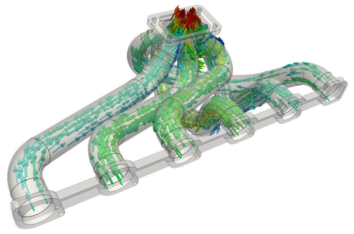
Internal flows: HVAC and Ductwork
Aerodynamics in HVAC (Heating, Ventilation and Air Conditioning) and pipe flow applications are also important. Here usually pressure losses are calculated as a result of viscous aerodynamic forces, separation at corners and bendings and sudden expansions.
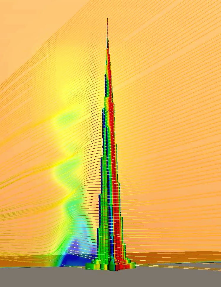
Wind Load on Buildings and Urban Aerodynamics
In the case of tall buildings and skyscrapers forces due to wind loads can be quite significant due to their large surface area. This can be handled as a “drag” force of the solid obstacle placed in the flow. Besides the wind load force on the structure, pedestrian comfort can be also assessed at lower levels. Separations on the structure as well as high-speed regions can affect humans, making it sometimes impossible to even walk. Building and urban aerodynamicists simulate those scenarios with CFD tools these days.
Wind Turbine
A very important technology towards sustainable energy resources is the wind turbine. As it usually consists of 3 aerofoils placed in an airflow, all the aspects of aerodynamics are present. Drag is used as a measure of the efficiency of the turbine, and lift as a measure of the power extracted from the wind. Moments are used to calculate the loads on the blades. SimScale provides a very interesting Project Spotlight about the optimization of wind turbine blades. Go and check it out if you are interested in finding out more about this interesting topic.
Hydrodynamics
As a very similar field to aerodynamics, hydrodynamics needs to be mentioned here as well. Hydrodynamics deals with liquid flows, mostly water. While usually incompressible and low speed, water flow experiences the same effects as airflow scenarios: boundary layers, turbulence, and forces acting on a solid body are also present. Hydrofoils and speedboats are designed through hydrodynamic CFD analysis.
Aerodynamics Using SimScale
SimScale offers a browser-based platform for simulation enthusiasts, where a CAD design can be meshed and simulated, and the results post-processed easily. The platform supports simulation of most of the transient or steady, compressible or incompressible aerodynamic flows. Additionally, you can have a look at the public projects and choose a case that fits your problem best, so you can get started even faster. In the simulation below you can see the air pressure contours behind a biker. It can be observed that a different biker would benefit by biking just behind him because of the low pressure zone and would need less power to keep the same speed.
References
- Von Karman, Theodore (2004). Aerodynamics: Selected Topics in the Light of Their Historical Development. Dover Publications. ISBN 0-486-43485-0. OCLC 53900531
- Anderson, John D. (1997). A History of Aerodynamics: And Its Impact on Flying Machines. Cambridge University Press. ISBN 0-521-45435-2. OCLC 228667184.
- Anderson, John D. (2007). Fundamentals of Aerodynamics (4th ed.). McGraw-Hill. ISBN 0-07-125408-0. OCLC 60589123.
- https://www.brockmann-consult.de/CloudStructures/karman-vortex-examples-9.htm
- Beginner’s Guide to Aerodynamics”, Grc.nasa.gov, 2021.
Last updated: February 16th, 2026
Did this article solve your issue?
How can we do better?
We appreciate and value your feedback.
What's Next
What is Viscosity?

