Wind Turbine blade, fluid and structural optimisation using CAE (Part 1)
Links
My Wind Turbine Optimisation Project
Original Forum Post
Contents
- Preface
- Introduction
- Conceptual design
- Modelling in OnShape
- Meshing in SimScale
- CFD Analysis in SimScale
- Post Processing and Analysis Results
- Optimisation based on results (Part 2)
- Structural design (Part 2)
- Structural optimisation in ST Inspire (Part 2)
- Structural analysis (Part 2)
- Transient simulation of final design (Part 2)
Preface
This project was originally a test for an aerofoil script I had written in OnShape. I designed the blade by incorporating different aerofoil profiles into a single blade and used guides to loft between them. This wasn’t as easy as I had originally envisioned and decided it would be a shame to let the design stop there, I needed to see if my calculations were valid after so much hard work.
My initial meshes failed and it took me a while to remember how to go about the setup, however with some input from SimScale staff and a previous example from the drone workshop I was on my way. I hit a few hurdles with the blade design, which is why the designs start with configuration 2. Due to this, I thought it would be good to include an overview to modelling the design in OnShape.
I have written about the design and optimisation approach I took; it was a learning experience and I most definitely didn’t get it right first time. However, it does show an approach I feel most students like myself would take and highlights why initial research is so important before jumping in and making a design in CAD.
Introduction
In this project I shall outline the mathematical models, simulations and data used to create the initial conceptual design. I will then explain how I created a 3D model from the concept in OnShape and then I will bring the design into SimScale to analyse it. Using this analysis, I hope to identify areas in which the design can be improved and iterate the design analysis workflow to produce an optimal blade design.
Once the aerodynamic optimisation is done, a further simulation will be done to generate data ready for a structural design and hopefully a bit of a contemporary optimisation using structural optimisation software ST Inspire.
As a lap of honour I will perform a transient analysis of the final aerodynamic shape and process the data to hopefully show some really interesting results.
Conceptual Design
My first calculation was the angle of the apparent wind at varying distances from the axis of rotation. Apparent wind is calculated from wind speed and tangential blade speed; the vector of the combined speeds is the apparent wind speed and direction. The angle between this vector and the normal of the blade is what was calculated. This is used to see how the blade should twist and how much this varies with different wind speeds. Obviously we cannot design a turbine to generate at high efficiency for every wind speed so a design range is needed. I chose to design between 5m/s and 20m/s because average wind speeds are approximately within these limits in the UK
The next thing that needed to be decided was the aerofoil profiles. Looking at the graph showing apparent wind angle the variance at the tip is around 16 degrees, whilst at the base it is a little less at around 12.7 degrees. The aerofoil at the tip therefore needs to be a little less sensitive to stall because we will pick the ‘middle ground’ angle and expect the blade to operate in the stall region at some wind speeds. As we may know, aerofoils with high camber have a more aggressive stall however they have good lift characteristics.
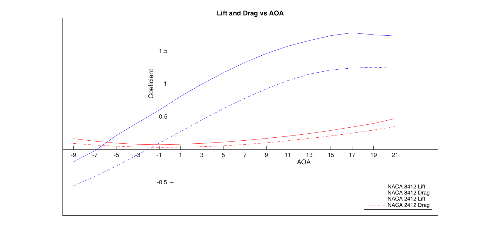
So I picked two aerofoils; one with high camber the area close to the centre and an aerofoil that has less camber for the tip. I modelled and simulated these profiles to discover their stall angles and angles of zero lift and generated lift curves for them.
Ideally the blade should be modelled so that at design speed the blade should produce zero lift at the tip and the base. This means the data collected about lift coefficients are needed to be analysed and the angle difference between zero lifts should be taken into account. Furthermore, for ease of 3D design it is worth subtracting the angle at which we can make the base angle zero.
Modelling in OnShape
This project was originally a test for a feature script I wrote in OnShape to produce an aerofoil from the NACA 4-digit standard using only a point for each of the leading and trailing edges, a selection of plane and the 4 digits required to define the aerofoil. The link to this publicly available script is provided below. Notice I am contemplating a blade creating script but I haven’t yet pursued this.
However, you will need the 3D spline script created by Llya Baran of OnShape (link below) to provide accurate drafting guides between the aerofoils once they have been created. I placed a 3D spline at ten point intervals along both upper and lower surfaces. This ensures the loft algorithms do not misinterpret the volumes between the aerofoils, especially if dramatic aerofoil size or angle changes happen.
The modelling process starts by placing planes at set distances from the origin at say 5 metre intervals starting at a couple of metres. On these planes create sketches of cord lines at the desired angles based on previous calculations and at the desired cord lengths and positions.
On these cord lines use the start and end vertexes to define the leading and trailing edge of each aerofoil. Using the camber profile at the base and the low camber profile at the tip, use linear interpolation between the tip and base aerofoils.
As previously described, add the 3D splines at set intervals ready for the loft. The more splines you add the better but there may be a point at which enough freedom isn’t given for the draft algorithms and draft failure may result.
Then select the draft tool and draft from the base profile progressively through each profile to the tip (order is important). Then add guide lines selecting each of your 3D splines. This should produce a very nice blade to base your design on.
Create a hub (or nose cone) and connect the blade to it. Split the connector so we can add angle in the assembly space. Use a circular pattern to add two more blades bringing the blade number to three. Create a cylinder around the blades; this will be the rotating zone when we import it into SimScale.
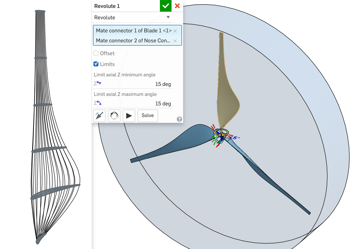
After the model has been designed an assembly has to be created. This is to allow the blade pitch to be altered and then imported to SimScale on many occasions; start by importing the hub and fixing it at the origin. Next import a blade 3 times and make each one a rotate joint on each of the blade-hub connectors adding limits of min=0, max=0. To alter the pitch the limits are simply altered to the desired angle then imported to SimScale. Finally import the enclosing cylinder and fix it to the origin. I usually make this cylinder transparent for easy checking of the model.
Meshing in SimScale
First set the pitch angle to ten degrees and go into SimScale, import from OnShape direct. Do this five times for angles of ten to thirty degrees. Create two geometric entity sets for the rotating volume and the blade and hub faces. Make sure that the blade face set does not include the interface surfaces i.e. the faces that connect the blade and the hub.
Next we will create a mesh that will be robust enough to mesh at every angle of attack. Start by selecting Hex-dominant parametric for CFD. Create a geometry primitive cylinder for the wake approximately a meter radius bigger than the rotating zone and trails for about 30 meters. Make the bounding box bigger than mine in width and add more height.
Use surface refinements to create a rotating cell zone, add layers, surface refinement, region refinement to the wake cylinder and a feature refinement particularly for that sharp trailing edge (I believe that is where my difficulties came in). If you need a place to start look at mine; I created an improved example called ‘Improved mesh’ to illustrate how I think it should look.
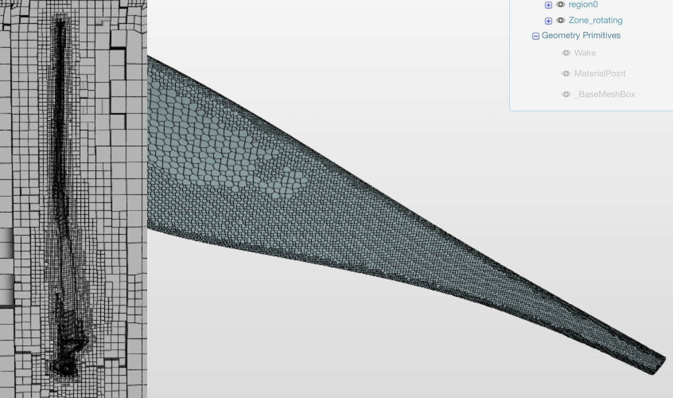
Its worth making sure the mesh is of good quality as each mesh is going to go through around six simulations if you get it right first time. I added a few extra snapping iterations and smoothing iterations however the most important thing is getting the refinements right.
After the meshes are completed inspect them to ensure the desired quality is present and add topological entity sets to make it easier to add boundary conditions later, I recommend defining inlet, outlet, blades, walls (slip) and ground (no-slip).
CFD Analysis with SimScale
Ideally we want to know how much torque is being produced (to calculate power P=𝛚𝛕) at different wind speeds and angles of blade pitch. After the results are collected, with the help of Matlab we can produce a nice surface plot showing power against angle and velocity.
First we will need to select analysis type; this will need to be incompressible (velocity is low) and we should definitely consider a turbulence model (I chose K-omega SST). This will prompt you to add a mesh under domain.
We must now define systems boundary conditions; velocity inlet, pressure outlet, define the top and sides as walls (slip) and the bottom as wall (no-slip). This bottom wall kind of simulates the ground and reduces velocity at the base of the blades slightly.
Now initial conditions must be set (I didn’t change much here except velocity).
Next the rotating zone needs to be set up under advance settings. Conveniently the rotation point is the origin and the rotating axis can be defined as the unit vector in the y-direction. The angular velocity direction is very important; use the right hand rule. In my case rotation was in the negative direction.
Finally, go to results control and add a forces and moments control item to the blades. This will be the main piece of data we get from the analysis.
Set up the numeric node accordingly and copy the simulation. Change the name, mesh and velocities accordingly to obtain a complete set of data. When running the mesh look at the convergence plots- sometimes they will settle but not reach their required accuracy. Chances are they wont and we may run an entire simulation and get the same results we did a quarter way through. After I have written the data twice; I check the forces and moments plot and if there is no change in the last few data points I stop the simulation to save time as the results can be considered accurate enough.
Results and Implications
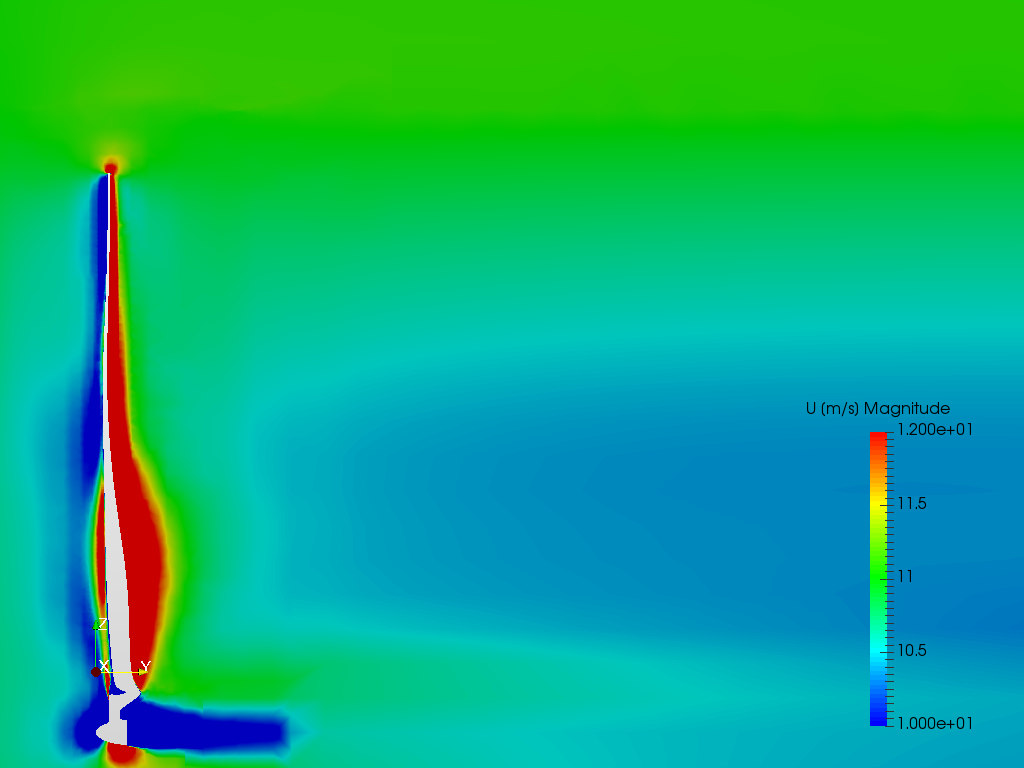
The most important results come from the pressure moments in the y-direction. Analysing and plotting these will give us a very good overview of how the design performs; from the graph we can see that at around 15 degrees’ pitch, the blade produces the most lift. But 10 degrees was meant to produce no lift, and max lift was going to be produced at around 25-30 degrees, so what is going on here?
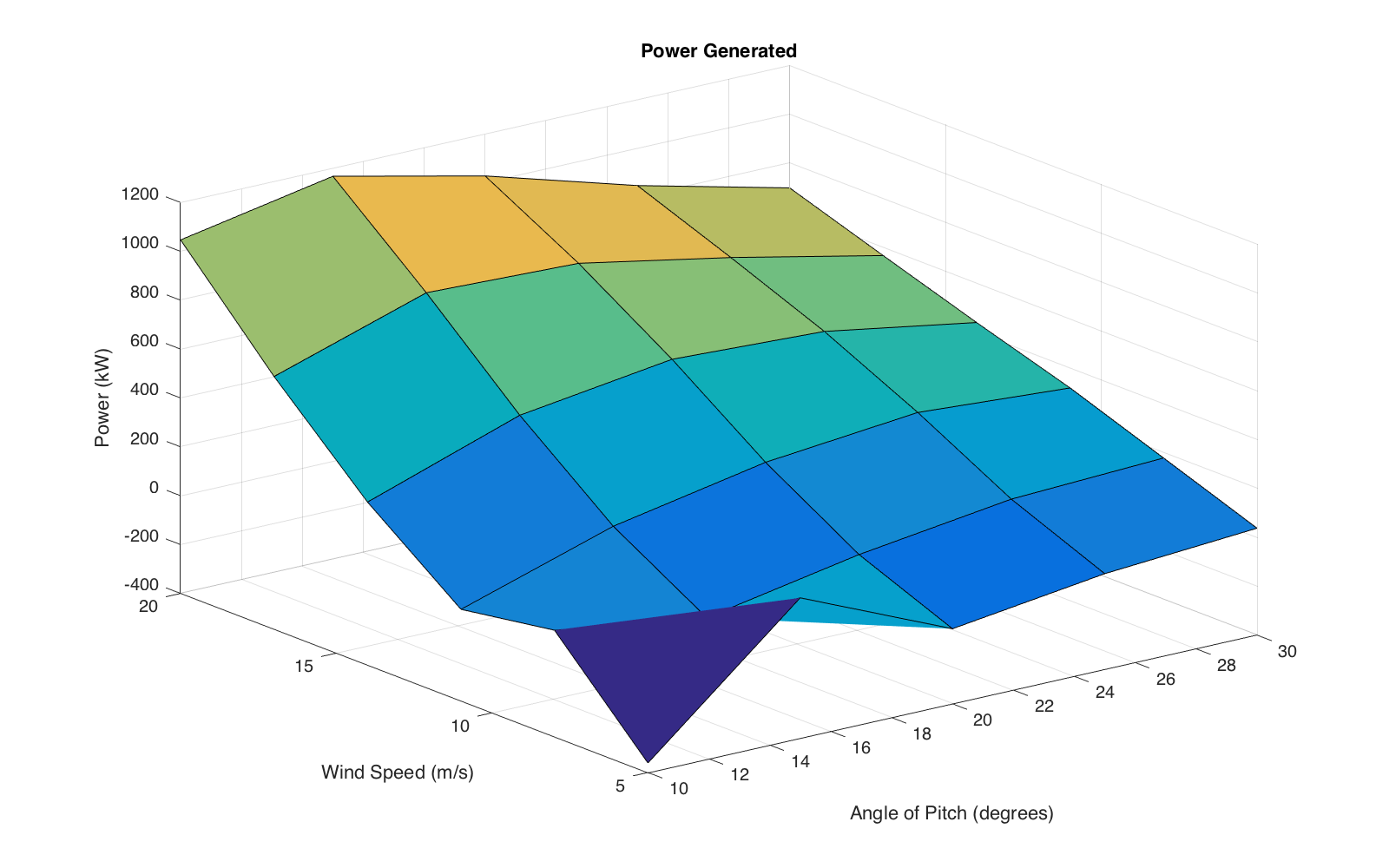
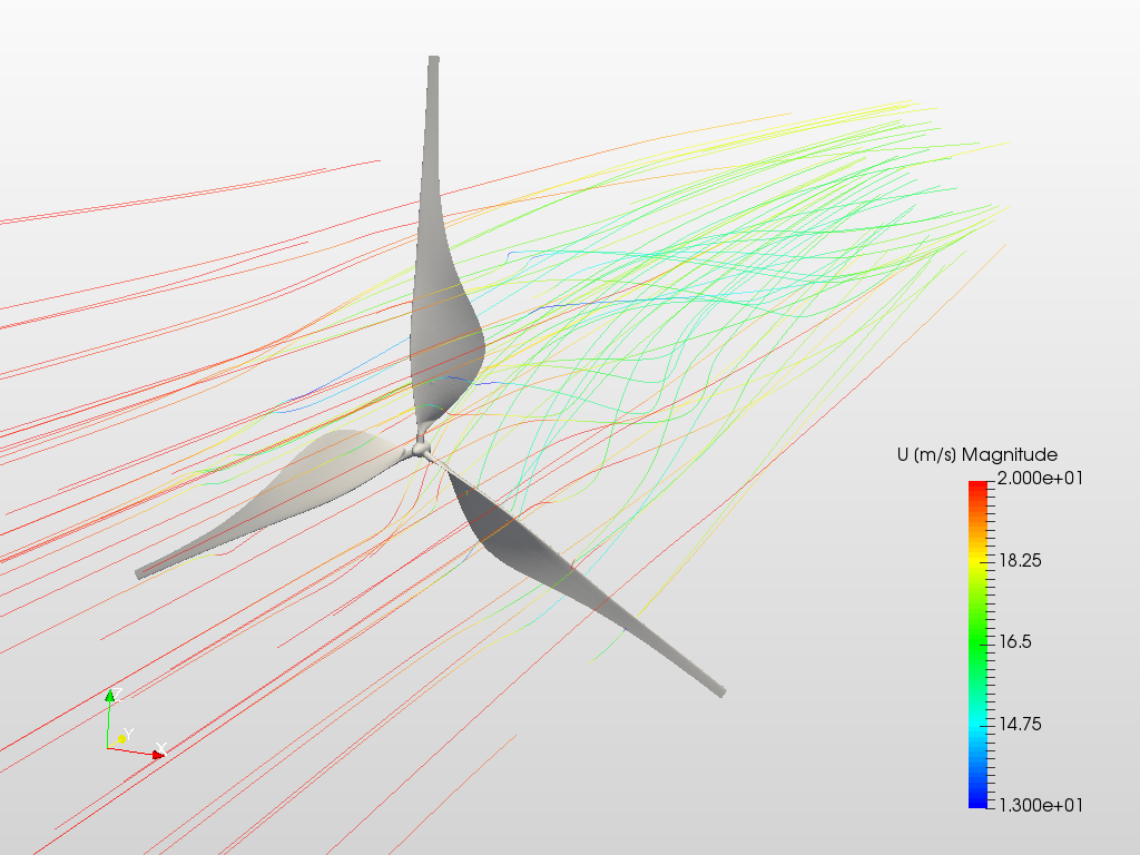
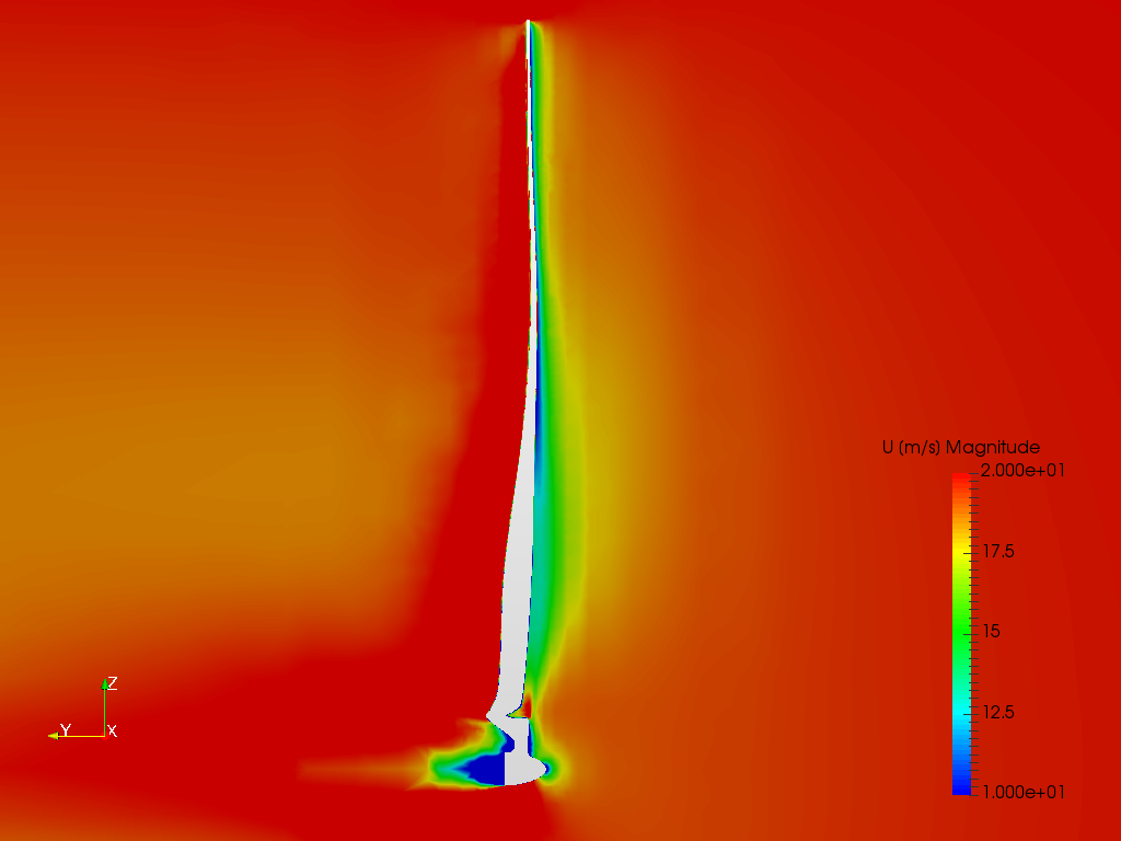
To find out we should look at the pressure on the surface of the blades to see where the lift is being generated. As we can see on the above animation there is negative pressure on top of the wing towards the tip of the blades but not much at the base. Looking closely at the cross sections below we can see the tip of the blade stalls just as the base starts creating pressure difference. So is
drag acting at the tips to counter lift generation at the base to produce the negative trend we see in the graph? I think so.
We did the maths and it didn’t work, so what went wrong? This is the point any engineer should check their calculations and pick up a book. After a little frustration, a lot of reading and some further number crunching I came up with the following theories;
- Wind velocity reduces before it gets to the blade ‘disks’ and thus alters the apparent wind direction.
- The tip speed ratio should be approximately between 4 and 10 (depending on design) and so my TSR of about 2.4was a little low. Increasing it to 3rad/s from 1.5 will bring TSR to approximately 6.5 puts us nicely in the middle of the ideal range.
So with these numbers I will redesign my blades this time with a larger nose cone, as I feel it maybe a bit small. I also intend to make the tips thin to a point to reduce lift induced drag.
Postface
The next write-up will be the analysis of the new and improved design. If anyone has any thoughts and comments on my next design before I go too far they will be welcome. Below are the links for the Introduction and the next write-up (when available) and if you want to read further into the theory, the two sources listed below are excellent starting places to gain an understanding on aerodynamic design of wind turbine blades.
Background Reading
Anon., n.d. Gurit. [Online]
Available at: http://www.gurit.com/files/documents/2aerodynamicspdf.pdf
[Accessed 01 August 2016].
Fahey, S., 2010. Wind Turbine Blade Aerodynamics. [Online]
Available at: www.sparweb.ca/1_Blades/Aero.html
[Accessed 13th August 2016].
\underline{\textbf{Visit our SimWiki by clicking on the picture}}

 - Johannes