Documentation
Preparing, uploading, and adapting your CAD model for simulation is the first step in setting up a simulation. CAD models cannot be created in SimScale but they can certainly be uploaded, cleaned, and prepared to begin the simulation. Some tips for CAD preparation and its proper upload are outlined below:
To upload a CAD file onto the SimScale Workbench:
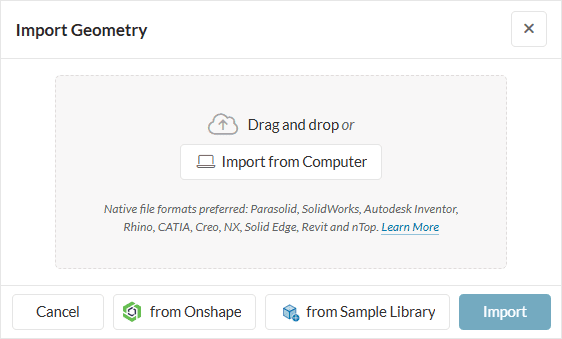
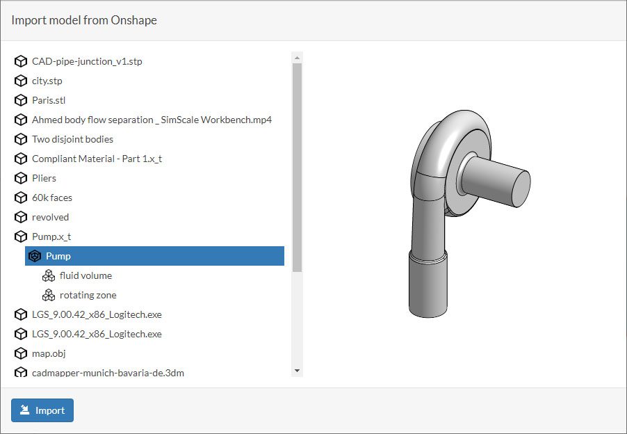
Another option is to use the ‘from Onshape’ button to directly pull a design from your Onshape library. Additionally, sample CAD models are available by selecting the ‘from Sample Library’ button.
The maximum size limit for uploading CAD models in the SimScale platform is 3 GB (gigabytes).
Important
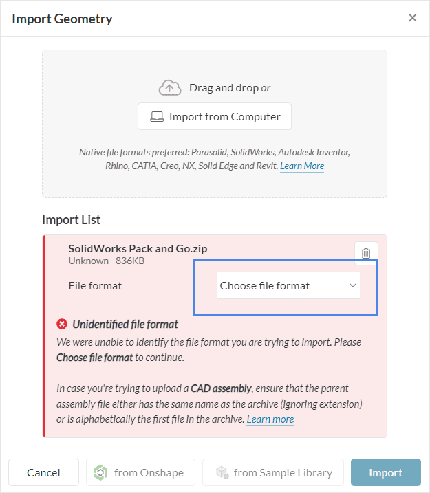
When importing zip files to SimScale, the File format needs to be selected. For example, in the case of a Pack and Go file from SolidWorks, select SolidWorks (.sldprt / .sldasm) from the drop-down menu.
Did you know?
SimScale also supports simulation using uploaded meshes. So if you already have a meshed geometry and simply want to get going with the setup we refer you to this page.
SimScale supports the following CAD formats:
Generally, it is recommended to upload the model in the native format of the tool it was created with (e.g. as .sldprt if modeled in SolidWorks). SimScale natively uses the Parasolid CAD kernel. In order to have all CAD manipulation functionality available within SimScale, the CAD model needs to be successfully translatable into the Parasolid format.
While uploading the CAD model, it undergoes optimization steps automatically to best suit the simulation. These steps are explained in detail below. Although not advisable, the user can turn these off if needed or desired.
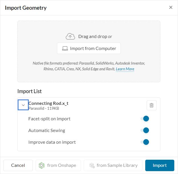
Facet-Split on Import
Facet models contain geometry that is not described by parametric functions but by a surface mesh consisting usually of triangles. Often the whole faceted geometry is stored in one big surface part and can not be easily accessed to define e.g. boundary conditions on separate faces. In order to do that you can split the faceted parts of the models by a surface angle. For all angles that are higher than the given value, the algorithm tries to separate the geometry by introducing separate faces. Some formats contain only faceted data, for e.g., *.stl files; others like Parasolid, Step or Rhino can contain mixed parametric and faceted parts. For parametric geometry, this setting doesn’t take any effect.
To control the facets fully…
To control the facets fully, toggle off Facet split on import and split the STL outside of SimScale by putting it to different STL files and upload everything as a zip file. The files will be translated as solids and the STL-solids will be translated as faces.
Automatic Sewing
Automatic sewing tries to connect parts of the model that are stored separately but touch exactly. In case a closed shell can be achieved, it additionally creates a solid body bound by the original faces. As most simulations are carried out on three-dimensional domains and require solid regions as input it is recommended to use this option on import.
Improve Data on Import
This option tries to improve the topology (e.g. edges, vertices) and geometry of the model by adjusting tolerances, simplifying entities, etc. As this option should improve CAD operations and data handling for all downstream applications it is recommended to use it on import. For very complex models it can take a considerable amount of time though, therefore you can also opt-out and reconsider in case you face issues in geometry handling or meshing.
Optimize for LBM / PWC
This option allows you to import a *.stl file that is optimized for the Incompressible LBM and Wind Comfort analysis types. It leaves out complex import steps like sewing and cleanup that are not required by the LBM solver and therefore also allows to import big and complex models fast.
To upload an assembly file from a particular CAD tool please collect all the related parts and sub-assembly files along with the assembly file and create a *.zip file. Then upload this *.zip file using the upload dialog. Find a detailed guide on assembly upload here. Currently, SimScale supports the assembly upload feature for the following formats:
| CAD Tool | Native Part format | Native Assembly format |
| CATIA | .CATPart | .CATProduct |
| Fusion 360 / Inventor | .ipt | .iam |
| SolidWorks | .sldprt | .sldasm |
| PTC Creo | .prt | .asm |
| Siemens NX | .prt | .prt |
Keep in mind!
If sub-assemblies exist, the software first checks if the archive name matches any assembly name in the archive – and we use this assembly as a root assembly of the import.
If not, it then checks the first assembly file alphabetically and uses this file as a root (parent) assembly of the import.
Note
In case round parts of your geometry appear to have corners, don’t worry: SimScale will automatically simplify your geometry for display purposes to make sure that you can fluently interact with the model. Internally, especially for the meshing process, SimScale uses the fully featured geometry.
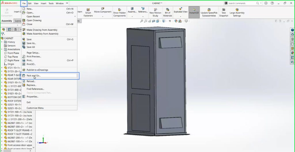
Some CAD tools, such as SolidWorks and Autodesk Inventor, have a Pack and Go functionality, which saves together all files related to a model design with correct references. This workflow is helpful when exporting complex assemblies (parent and child assembly) since it handles the structure of the export file automatically.
The image below shows the steps to use the Pack and Go functionality on SolidWorks:
After navigating to Pack and Go, a second window opens with more options. Here, enabling the Save to Zip file option is important:
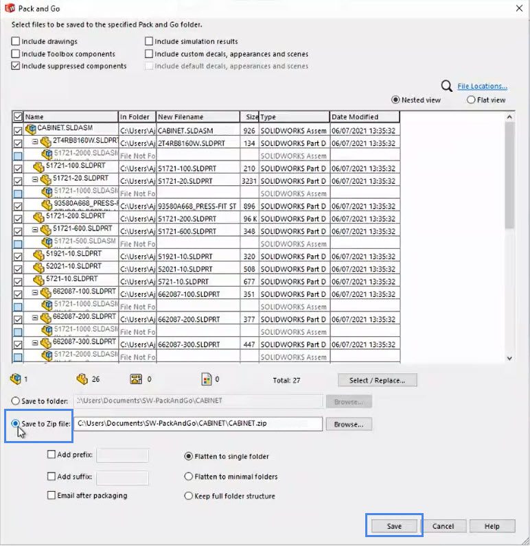
After saving, the Pack and Go zip file can be directly imported to the SimScale platform. Don’t forget to select the proper file format for the zip file to upload.
Importing implicit geometries from nTop works similarly to the assembly upload workflow, but requires an additional preparation step for entity assignments in the simulation workflow.
To import the prepared model, add all bodies to a compressed archive (zip, tar.gz) and upload it to SimScale. All subsequent workflow steps work exactly as for parametric or faceted models.
To enable a seamless design workflow, SimScale offers direct integration with a couple of CAD modeling tools. These integrations allow the direct import (via push/pull) of your designs into SimScale.
The SimScale Connector App for Onshape allows you to quickly import your CAD models directly from your Onshape account into the SimScale simulation platform without the need of exporting and uploading files.
Create your model on Autodesk Fusion 360 and with a few clicks push your geometry to an existing project on SimScale without having to leave the application or do cumbersome format conversions when saving the models you want to use in your simulations.
To download, visit the Fusion 360 app store:
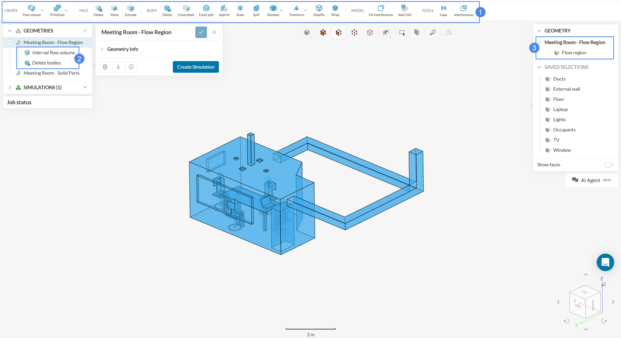
After CAD upload, some additional preparation might be required. SimScale offers a dedicated environment to interact with your model called ‘CAD Edit’ that helps you optimize the model within SimScale without having to switch to other CAD software. Try this feature today.
The CAD Edit supports many operations like scaling, extrude, body and face delete, surface splitting, flow volume extraction, etc. Users can access the CAD Edit from the workbench itself by clicking on the CAD in the Geometry tree. This brings up the CAD tool bar allowing editing in place. The modified geometry can be seamlessly updated in simulations with only one click.
Depending on the complexity and quality of your CAD model, some preparation and cleanup work might be required. Most of this cleanup work can be done within SimScale using the available CAD operations. The following general guidelines might help get you to the first successful iteration of your simulation.
Diving deeper, keep in mind the following requirements for a successful and accurate simulation:
The dimension of the model is very important for the simulation. If there are any discrepancies between the model units and the SimScale units this can lead to unrealistic geometrical dimensions. In this case, it is crucial to perform a scaling operation.
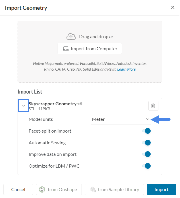
The default dimension used within the Workbench is Meter. The user can change it to other units from the dropdown as shown above although this option is only available for .stl files that do not contain unit information in the file.
Very often the CAD model can be simplified to get more accurate simulation results in a shorter time. A few cases for potential optimization are listed below:
CAD models often contain many detailed features because of manufacturing constraints or the installation. Good examples are small holes or windings. These detailed features might be relevant for the final manufacturing but they do not affect simulation results, rather only increase the meshing and computing time significantly. Therefore, such features should be removed.
Small entities can be a problem when it comes to meshing. If there are very small faces with sharp angles the surface meshing might fail. An example is demonstrated below, where faces had to be merged before a surface mesh could be generated. Such small entities should also be removed during CAD preparation.

If the problem is symmetric, computation time can be significantly reduced by using symmetry boundary conditions and performing simulations on just a part of the whole CAD model. In such a case only one instance of the symmetric parts of the model should be imported.
Analyzing smaller parts of the CAD one by one, rather than analyzing the entire CAD in a single simulation, can help reduce the complexity of the problem and speed up the simulation.
When performing a simulation with rotating parts, such as pumps and turbines, rotating zones need to be created as a part of CAD preparation. This requires some additional steps including CAD Edit before using the model for simulation. You can find a detailed approach to CAD preparation in the following article:
In case your model could not be successfully translated into the SimScale-specific internal format, all entities that failed translation will be exposed after upload. In order to progress further, try fixing all faulty parts and upload the model once more.
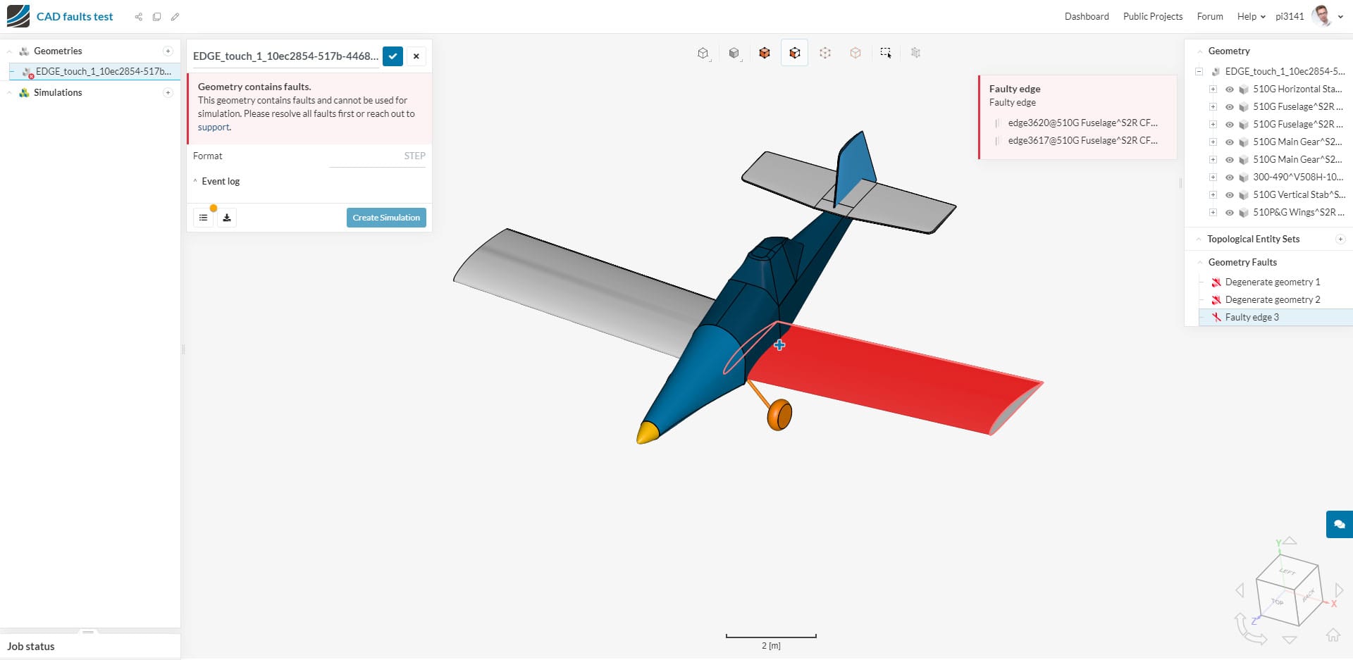
Refer to our knowledge base article on how to find faults in your CAD model.
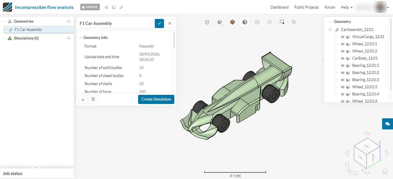
In general, a CAD model consists of different types of topological entities such as solids, faces, edges, and vertices. It’ is important to be aware of this topology as it will have an impact on mesh generation and simulation setup. Find an introduction to CAD topology here.
Still not satisfied? Looking for case-specific information? Visit the CAD PREPARATION section of our Knowledge Base articles.
Last updated: June 12th, 2026
We appreciate and value your feedback.
What's Next
Simulation Setuppart of: Simulation Setup
Sign up for SimScale
and start simulating now