CAD Topology
To run a simulation on a CAD model, the model must fulfill somewhat more restrictive criteria than one might be used to. Since a mesh needs to be generated, it is not enough that the CAD model just looks correct. Therefore, some CAD cleaning may be required, as discussed under CAD preparation, but also some topological aspects may need to be considered. Here you can find some hints about them.
Why is topology important?
For a correct and efficient simulation setup, you should ensure that your CAD model has the right CAD topology for the simulation to run. Generally, a CAD model consists of different topological entities such as solids, faces, edges, or vertices. You should be aware of this topology since it will impact how the mesh is generated.
What is Topology?
Most of the CAD models are described using the B-Rep method, which describes shapes using limits. A B-Rep model is composed of two parts: Topology and geometry. But what is the difference between geometry and topology in CAD?
- Topology describes how elements are bounded and connected.
- Geometry describes the shape of each element.
When thinking about CAD geometry vs topology, geometry is the quantifiable information, while topology is the shape that is created by the geometry. If the CAD geometry scale is changed, the geometry values would be changed, but the topology would not.
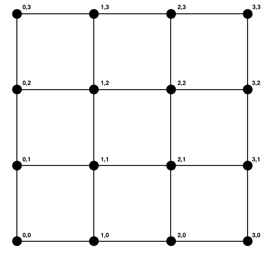
If we take the example of a simple three cells by three cells grid mesh with the line intersections being nodes: The geometry information would be the coordinates of the line intersections or nodes, and the topology would be the information about the lines; in other words, which nodes are connected together.
Depending on how you built your CAD model and the type of software you are using, the topology of your CAD model might be described differently. For a successful meshing and simulation setup, it is of great help to be aware of the topology of your CAD model in advance. That way, you won’t waste time building the mesh only to realize later that it is either inaccurate or doesn’t support the simulation.
Topological Entities
Solids
To run a simulation based on a volume mesh, your CAD model needs to contain solids. The meshing algorithm will detect them automatically and will be able to create volume meshes for it.
Please note that a CAD model can contain either one solid (= part) or multiple solids (= assembly). This is relevant, for example, if you plan to run a structural simulation. If you are dealing with an assembly, each solid will be meshed as a single mesh, such that you need to connect these solids later via contact constraints to get a valid simulation.
Another way is to convert the whole assembly into a single part in the CAD software itself before meshing it, although make sure that this doesn’t interfere with the physics of the simulation. For a single solid mesh, this won’t be necessary.
A CAD model with a single solid is shown in Figure 2 below. The tree on the top right shows that only a single solid is present.
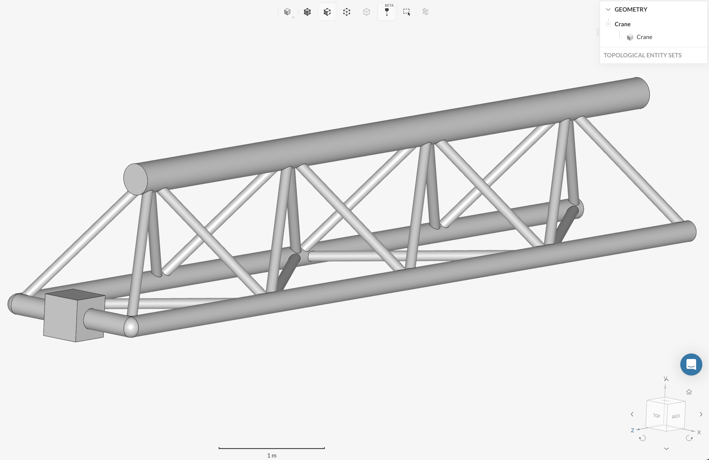
On the other hand, SimScale can also deal with complete assemblies. Have a look at Figure 3 below. This time the tree shows multiple solid parts.
Faces
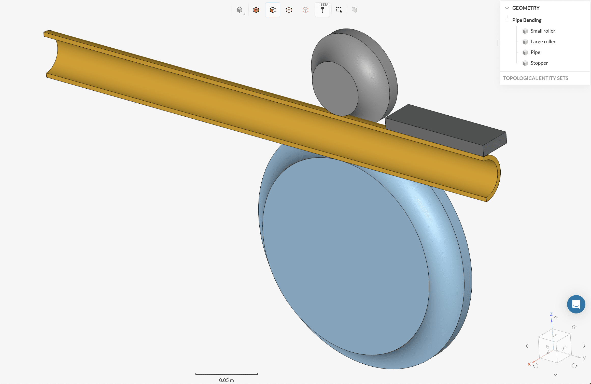
Sometimes a CAD model might only consist of faces and no solids at all. Such a model cannot be used to create a volume mesh.
It looks the same as a solid model. However, you should always refer to the tree on the right to see the topological information. The “shell” indicator name in the above image shows that this model does not contain any solid information.
Edges
Mathematically speaking, an edge is a line segment between two points or formed due to the intersection of two or more surfaces. The edge characteristics of a CAD model are heavily influenced by the type of file format in which it is either created or imported into simulation software.
Small features like holes or windings increase the edges count and also give rise to sharp angles and small faces. Such features are generally not crucial from the simulation viewpoint and should be removed. This process is also called CAD cleaning.
Vertices
A vertex represents a point in space. The edges of the CAD geometry intersect into a vertex. These vertices are also referred to as nodes. Load boundary conditions in FEA can be assigned using these nodes. Hence a well defined topological information about the nodes will help to set up an accurate simulation.

Last updated: August 11th, 2023
Did this article solve your issue?
How can we do better?
We appreciate and value your feedback.
What's Next
What is a Mesh?

